Downhole gas-liquid separation device and its working method
A technology of gas-liquid separation device and working method, which is applied in the direction of separation method, separation device, chemical instrument and method, etc., can solve the problems of no reduction in operation cost, expensive gas-liquid two-phase motor, and increased maintenance difficulty, so as to avoid motor Effects of damage, small amount, and simple structure
- Summary
- Abstract
- Description
- Claims
- Application Information
AI Technical Summary
Problems solved by technology
Method used
Image
Examples
specific Embodiment approach
[0031] Such as Figures 1 to 4 As shown, the downhole gas-liquid separation device includes a cylindrical body 1 , and a positioning wheel 2 is fixedly installed in the body 1 .
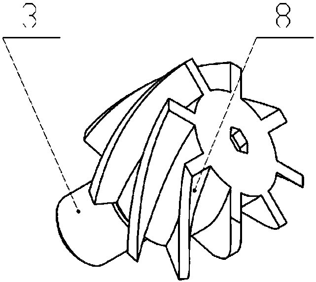
[0032] A rotatable swirl wheel 3 is installed on the positioning wheel 2, the swirl wheel 3 is provided with a spiral wheel piece 8, and the positioning wheel 2 is provided with a fluid channel.
[0033] The main body 1 is connected with a lower joint 4, and the inner end of the lower joint 4 located in the inner cavity of the main body 1 is provided with a shunt joint 5, and the center of the shunt joint 5 is coaxially provided with an air outlet channel 6, and the outer side is provided with a liquid discharge channel 7.
[0034] A space is provided between the swirl wheel 3 and the flow splitter 5, and the inner chamber of this section of the body 1 serves as a working chamber for gas-liquid separation.
[0035] Connect the upper end of the main body 1 to the coiled oil pipe, and connect the lowe...
Embodiment 2
[0038] The structure of embodiment two is basically the same as that of embodiment one, the difference is:
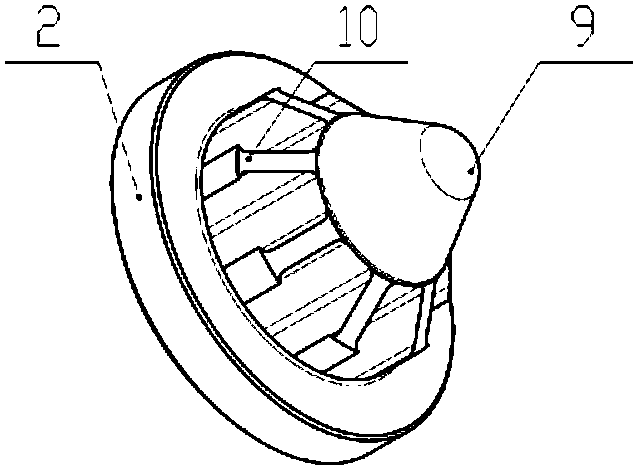
[0039] Such as figure 2 As shown, a protrusion 9 is provided on the outer side of the positioning wheel 2, and the protrusion 9 is in the shape of a truncated cone, and the top is arc-shaped, which is more conducive to spreading the pump liquid. The protrusions 9 are provided with deflectors 10 at intervals, and there are multiple fluid passages, all of which are located between adjacent deflectors 10 .
[0040] When the pump liquid passes through the positioning wheel 2, the protrusion 9 breaks up the pump liquid, and the deflector plate 10 further disperses the pump liquid, and the pump liquid finally enters the corresponding fluid channel through the gap between the deflector plates 10 , and then leave positioning wheel 2.
Embodiment 3
[0042] The structure of embodiment three is basically the same as that of embodiment one, the difference is:
[0043] Such as Figure 4 As shown, the distribution joint 5 is in the shape of a truncated cone, there is a gap between the outer wall of the distribution joint 5 and the inner wall of the body 1 , and an annular flange 11 is provided on the outer wall of the distribution joint 5 .
[0044] Under the action of centrifugal force, the liquid phase in the pump injection fluid flows along the inner wall of the working chamber of the main body 1, then flows into the space between the outer wall of the tap 5 and the inner wall of the main body 1, completely fills the space, and finally passes through The annular flange 11 enters into the drain channel 7 below. The liquid phase of the pump injection liquid is completely filled, and the gap between the outer wall of the shunt joint 5 and the inner wall of the body 1 is sealed. The gas left in the middle under the action of c...
PUM
 Abstract
Description
Claims
Application Information
 - R&D
- Intellectual Property
- Life Sciences
- Materials
- Tech Scout
- Unparalleled Data Quality
- Higher Quality Content
- 60% Fewer Hallucinations
Browse by: Latest US Patents, China's latest patents, Technical Efficacy Thesaurus, Application Domain, Technology Topic, Popular Technical Reports.
© 2025 PatSnap. All rights reserved.Legal|Privacy policy|Modern Slavery Act Transparency Statement|Sitemap|About US| Contact US: help@patsnap.com


