
Split sharps collection device

A collection device and split-type technology, applied in the field of medical appliances, can solve problems such as waste of resources and costs, and achieve the effect of saving costs and avoiding waste

Inactive Publication Date: 2018-01-23
THE SECOND AFFILIATED HOSPITAL ARMY MEDICAL UNIV
View PDF6 Cites 6 Cited by
  • Summary
  • Abstract
  • Description
  • Claims
  • Application Information

AI Technical Summary

Problems solved by technology

The problem is that since the stepper motor, infrared sensor and stepper motor driver are all installed on the box body of the sharps box, these electrical components will be disposed of as garbage along with the box body, which will inevitably cause a waste of resources and costs. waste

Method used


Image

  • Split sharps collection device
  • Split sharps collection device
  • Split sharps collection device

Examples


Embodiment 1

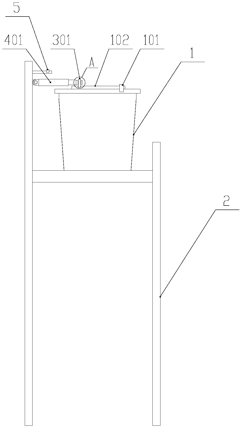
[0020] like figure 1 As shown, the sharps box 1 is placed on the bracket 2, and the height of the top of the sharps box 1 from the ground is 85-95cm, which is enough for medical staff, especially female medical staff, to accurately dispose of garbage without bending over.

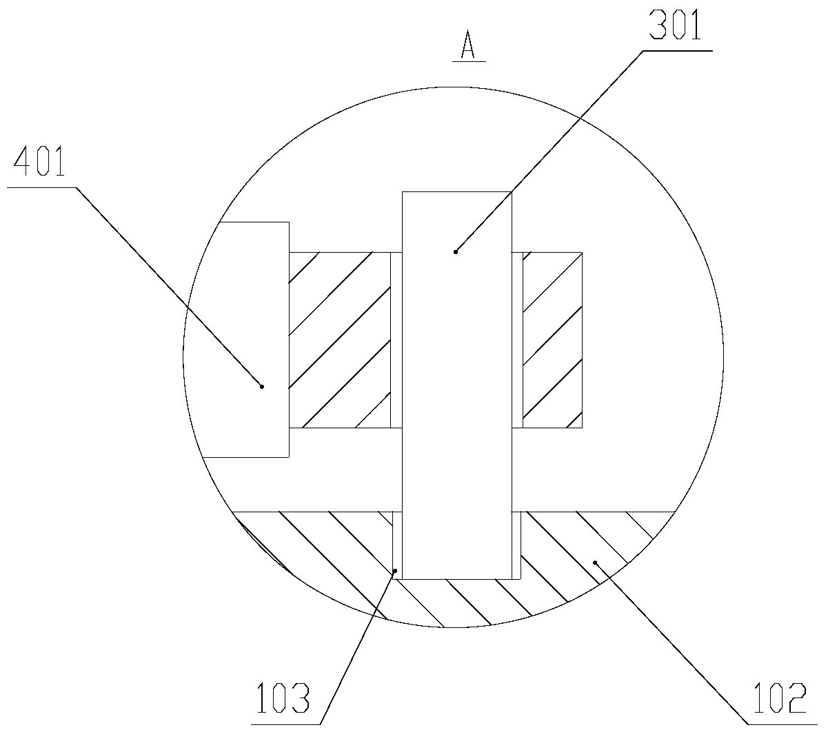
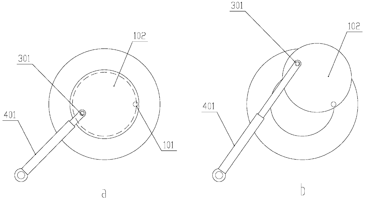
[0021] The top of the sharps box 1 has a top cover 102, and the top cover 102 rotates horizontally around the pivot 101 on the box body of the sharps box 1 to realize the opening and closing of the sharps box. The top cover 102 is provided with a blind hole 103 downwards from the top, and a swing cylinder 401 is installed on the support 2. The output end of the swing cylinder 401 is a ball hinge earring, and the ball hinge earring is connected with the blind hole 103 through a pin shaft 301, that is, a pin The shaft passes through the ball hinge earring and is inserted into the blind hole 103 , and there is a gap between the pin shaft 301 , the ball hinge earring and the blind hole 103 , and the pin shaft 3...

Embodiment 2

[0025] The difference from Embodiment 1 is that in this embodiment, the swing rod 311 and the connecting rod 312 are used as the connecting part for driving the top cover 102 to swing, and the motor 402 is used as the driving part for driving the connecting part. Concrete scheme is as follows: connecting rod 312 comprises fixed rod 313, movable rod 314 and the stigma 315 that integrally connects movable rod 314 below, fork 311 one end is driven to rotate by motor 402, and the other end is hinged with an end of fixed rod 313, and the fixed rod 313 The other end is hinged with one end of the movable rod 314 through a spring hinge 316 , and the stud 315 is located at the other end of the movable rod 314 . When the movable rod 314 is in a natural state, the stud 315 is inserted into the blind hole 103 in the form of clearance fit. To make the stud 315 leave the blind hole 103, the movable rod 314 needs to be swung upward against the resistance of the spring hinge 316 . The swing r...


PUM


Abstract

The invention discloses a split sharp instrument collecting device, which comprises a sharp instrument box and a support frame for carrying the sharp instrument box, wherein a pivot and a top cover capable of swinging around the pivot so as to open or close the sharp instrument box are arranged on the sharp instrument box; a blind hole is downwards formed in the top cover from top; a connecting element capable of driving the top cover to swing is separately connected with the top cover through the blind hole; and the connecting element is driven by a driving element arranged on the support frame. The driving element and the connecting element are separated from the top cover of the sharp instrument box; when rubbish in the sharp instrument box reaches the specified volume, the connecting element is separated from the sharp instrument box; the sharp instrument box is directly removed out from the support frame and is taken away for disposal; and the driving element for driving the top cover of the sharp instrument box and the connecting element can be continuously used for a new sharp instrument box, so that the waste is avoided, and the cost is reduced.

Description

technical field [0001] The invention relates to the field of medical appliances, in particular to a split-type sharps collection device. Background technique [0002] The sharps box is a kind of medical waste collection device, which is used to hold needles of disposable items such as syringes and infusion sets, various blades, scalp needles, suture needles, ampoules, small glass and other sharps, and is also used to collect sharps such as blood The entire set of syringes, blood transfusion sets, blood bags and other medical equipment that come into contact with blood. [0003] CN201420431640.3 of the applicant discloses an infrared induction sharps box, including a sharps box with a cover, a stepping motor, an infrared sensor and a stepping motor driver are arranged on the box body of the sharps box, and the stepping motor The cover is driven to open and close through the connection part, and the infrared sensor senses the hand of the doctor and controls the stepping motor...

Claims


Application Information

Patent Timeline
Patent Type & Authority Patents(China)
IPC IPC(8): A61B50/36
CPCA61B2560/04
Inventor 代丽王苹曾燕琴甘雪梅吉红霞何丽周萍陈胜高瑞
Owner THE SECOND AFFILIATED HOSPITAL ARMY MEDICAL UNIV
Learn More