
A sliding door steamer

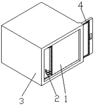
A technology for sliding doors and steaming cabinets, applied in the field of kitchen utensils, can solve problems such as deformation and damage to the sealing effect, and achieve the effects of large opening range, realization of sealing function, and convenient pulling and pulling.

Active Publication Date: 2017-10-27
乐科工业设备有限公司
View PDF5 Cites 0 Cited by
  • Summary
  • Abstract
  • Description
  • Claims
  • Application Information

AI Technical Summary

Problems solved by technology

[0002] Steaming and stewing food with high-temperature steam is fast and efficient, but the steaming cabinet needs to bear a certain pressure; the current steaming cabinet generally adopts a revolving door structure: one side of the door panel is hinged to the cabinet body, and the other side is connected to the cabinet body through a lock , Install sealing strips around the door. After the door panel and the cabinet are locked, the gap between the door panel and the door is closed by the sealing strip, so that the steam in the steamer does not leak; the defect of this technology is: when the steam is high temperature and high pressure , the door panel will be deformed due to greater pressure, destroying the sealing effect

Method used


Image

  • A sliding door steamer
  • A sliding door steamer
  • A sliding door steamer

Examples


Embodiment Construction

[0028] The technical solutions in the embodiments of the present invention will be clearly and completely described below in conjunction with the accompanying drawings in the embodiments of the present invention. Obviously, the described embodiments are only some, not all, embodiments of the present invention. Based on the embodiments of the present invention, all other embodiments obtained by persons of ordinary skill in the art without making creative efforts belong to the protection scope of the present invention.

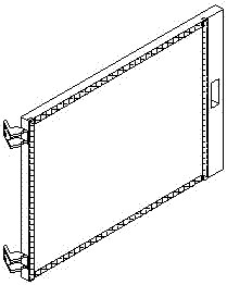
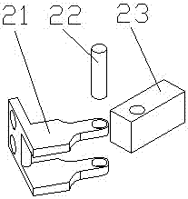
[0029] Such as Figure 1-10 As shown, a steam cabinet with a sliding door includes a box body 3, a door panel 1 movably connected with the box body 3, and a hinge 2 installed on the door panel. The door slot 303, the left end of the opening end of the box body 3 is provided with a sealing groove matching the left end face of the door panel, the door panel 1 slides in the door slot 303 and realizes the opening and closing function of the door panel 1, and the hin...


PUM


Abstract

The invention discloses a steam cabinet provided with a sliding door. The steam cabinet comprises a box body, a door plate movably connected with the box body and hinges mounted on the door plate, each hinge comprises a movable hinge piece, a fixed hinge piece and a hinge shaft, each movable hinge piece is hinged to one end of the corresponding fixed hinge piece through the corresponding hinge shaft, the other end of each fixed hinge piece is fixedly connected with a corresponding hinge mounting groove formed in the left end side of the door plate, each movable hinge piece comprises a plate-shape gripper and wing plates which are arranged at the same end side of the plate-shape gripper and are parallel to each other, each wing plate comprises a guiding portion and a limiting portion, arc-shaped end faces used for guiding are arranged on the inner end face and the outer end face of each guiding portion, each guiding portion is provided with a through hole matched with the hinge shaft, the inner end face and the outer end face of each limiting portion are horizontal planes, a side opening matched with the inner end faces and the outer end faces of the limiting portions in width is formed in the right end of an open end of the box body, and positioning holes are formed in each plate-shaped gripper; a plate-shaped hinge poking block corresponding to a gap between the two corresponding wing plates is arranged on the inner wall of the left side of the box body, and hinge positioning nails corresponding to the positioning holes in the plate-shaped grippers are mounted on the inner wall of the right side of the box body.

Description

technical field [0001] The invention relates to the technical field of kitchen utensils, in particular to a pressure steamer. Background technique [0002] Steaming and stewing food with high-temperature steam is fast and efficient, but the steaming cabinet needs to bear a certain pressure; the current steaming cabinet generally adopts a revolving door structure: one side of the door panel is hinged to the cabinet body, and the other side is connected to the cabinet body through a lock , Install sealing strips around the door. After the door panel and the cabinet are locked, the gap between the door panel and the door is closed by the sealing strip, so that the steam in the steamer does not leak; the defect of this technology is: when the steam is high temperature and high pressure , the door panel will be deformed due to greater pressure, destroying the sealing effect. Contents of the invention [0003] In order to solve the deficiencies of the prior art, the object of t...

Claims


Application Information

Patent Timeline
Patent Type & Authority Patents(China)
IPC IPC(8): A47J27/16A47J36/00
CPCA47J27/16A47J36/00
Inventor 李传聪
Owner 乐科工业设备有限公司
Learn More