
Full-automatic washing machine

A fully automatic washing machine and washing machine technology, applied in the field of washing machines, can solve the problems of cross-infection of laundry, affecting the washing effect of clothes, etc., and achieve the effects of avoiding cross-infection, saving washing costs, and using hygienic use.

Pending Publication Date: 2016-04-27
QINGDAO HAIER WASHING MASCH CO LTD
View PDF4 Cites 7 Cited by
  • Summary
  • Abstract
  • Description
  • Claims
  • Application Information

AI Technical Summary

Problems solved by technology

These molds are caused by a large amount of dirt accumulated inside the washing machine that has been used for a long time and cannot be effectively removed to breed and reproduce. If the dirt that is invisible to the user is not removed, the bacteria will adhere to the clothes again after the next wash. Brought to the human body, causing the problem of cross-infection in laundry
[0006] In addition, since the lint floats in the water when the washing machine is washed, using the existing drainage method, the water is discharged from the lower part of the inner tub, and finally the lint will remain on the clothes, affecting the washing effect of the clothes

Method used


Image

  • Full-automatic washing machine
  • Full-automatic washing machine
  • Full-automatic washing machine

Examples


Embodiment 1

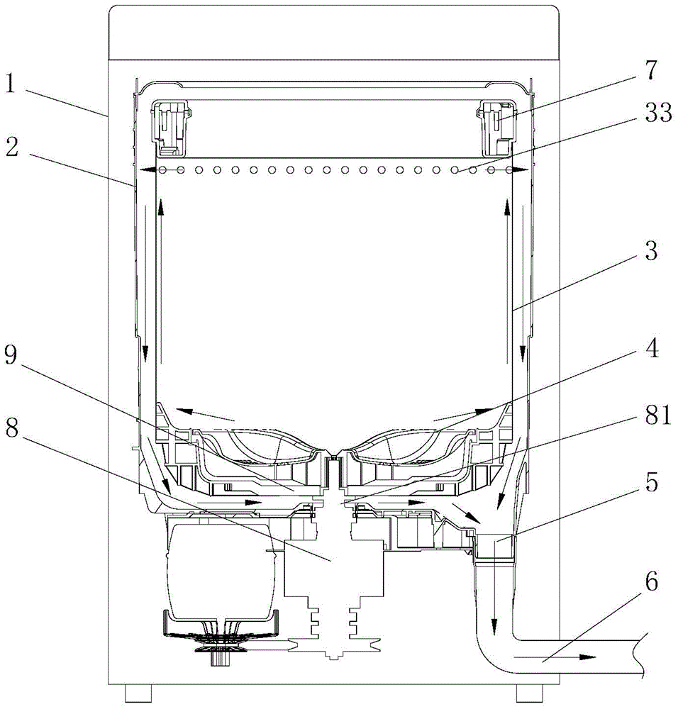
[0051] Such as Figure 4 As shown, the water outlet hole 33 described in this embodiment is located in the area between the lower edge of the balance ring 7 on the barrel body 31 and the position where the maximum water intake of the washing machine is set.

Embodiment 2

[0053] Such as Figure 5 As shown, the bucket body 31 of the present invention is provided with a drainage waterway structure for supplying water from the bottom 32 of the inner bucket to the upper water outlet hole 33 .

[0054] The barrel body 31 described in this embodiment has a rounded platform structure with a thick top and a thin bottom. The peripheral wall of the barrel body 31 and the axis of the inner barrel have an inclined angle α, and the included angle α is not greater than 4°; preferably 1°-2°. The barrel body 31 below the balance ring is provided with one circle or multiple circles of water outlet holes 33 arranged up and down.

Embodiment 3

[0056] Such as Figure 6 As shown, the difference between this embodiment and the above-mentioned second embodiment is that: the inner barrel body 31 is a cylindrical structure, and an outwardly protruding drainage groove 34 is provided on the barrel wall, and a water outlet 33 is located in each drainage groove 34 top. The opening of the drainage groove 34 faces the center of the barrel body 31, and the depth of the drainage groove 34 gradually deepens upwards from the bottom of the barrel body 31, that is, the bottom wall of the drainage groove and the inner barrel axis have an angle β inclined outwards, and the angle β 1°-2°.

[0057] Further, the side wall of the drainage groove 34 transitions smoothly with the surrounding wall of the barrel body 31 and the bottom of the drainage groove. Furthermore, the bottom end of the drainage groove 34 directly transitions smoothly with the surrounding wall of the barrel body 31 .

[0058] Preferably, the bottom of the drainage gro...


PUM


Abstract

The invention discloses a full-automatic washing machine. The full-automatic washing machine comprises an outer drum and an inner drum disposed inside the outer drum; a drainage port is arranged at the bottom of the outer drum; the drainage port of the outer drum directly communicates with a drainage pipe; and a driving device used for driving the inner drum and impellers to work is arranged below the outer drum. The inner drum comprises a drum body, an inner drum bottom arranged at the lower portion of the drum body, and a balance ring arranged at the upper opening of the drum body. The upper portion of the inner drum is provided with water outlets. The portion, below the water outlets, of the inner drum is sealed and does not leak. The drum body is provided with a drainage channel through which the water obliquely and upwardly moves to the water outlets from the bottom portion of the inner drum. The washing machine employs the inner drum to hold water for washing, so that water can be saved. Through an upper portion dewatering and dehydrating manner, the washing water is directly discharged sequentially through water outlets in the upper portion of the inner drum, the outer drum, the drainage port of the outer drum and the drainage pipe along the drainage channel, and water flows upwardly through the high-speed rotation of the inner drum and then is discharged from the water outlets, so that lint floating in the water cannot be left on the clothes and can be entirely discharged, and the clothes can be more cleaner.

Description

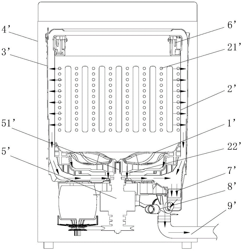
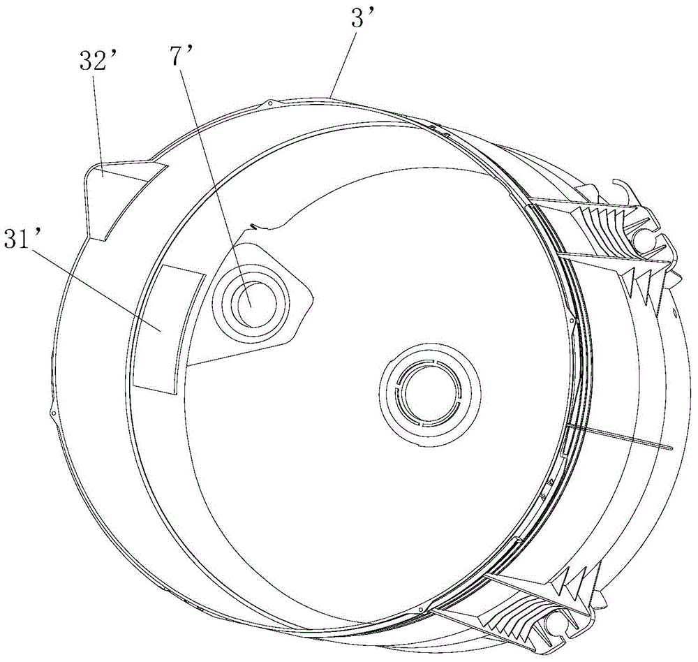
technical field [0001] The invention relates to the field of washing machines, in particular to a fully automatic washing machine, especially a fully automatic washing machine without a drain valve. Background technique [0002] Existing pulsator washing machines, such as figure 1 As shown, it generally includes a pulsator 1', an inner barrel 2', an outer barrel 3' and a box body 4' arranged in sequence from the inside to the outside, wherein the pulsator 1' is arranged at the bottom center of the inner barrel 2' and can be driven by a driving device 5 ' Drive the rotation. The top of the inner tub 2' is provided with a balance ring 6', and the side wall of the inner tub 2' is longitudinally provided with multiple rows of dewatering holes 21', and the bottom of the inner tub 2' is provided with a drain hole 22', which is also The output shaft 51' of the driving device 5' is passed through. Such as figure 2 As shown, an air chamber 31' and a water level sensor (not shown...

Claims


Application Information

Patent Timeline
Patent Type & Authority Applications(China)
IPC IPC(8): D06F37/12
Inventor 吕佩师程宝珍
Owner QINGDAO HAIER WASHING MASCH CO LTD
Learn More