
Peeling device and peeling method for display substrate

A technology for display substrates and peeling devices, which is applied in optics, instruments, electrical components, etc., can solve the problems of separation failure, failure to achieve separation of glass substrates and flexible display substrates, and achieve high success rate and high separation success rate.

Active Publication Date: 2016-04-20
BOE TECH GRP CO LTD
View PDF8 Cites 21 Cited by
  • Summary
  • Abstract
  • Description
  • Claims
  • Application Information

AI Technical Summary

Problems solved by technology

[0004] However, since the flexible display substrate and the glass substrate are still in a relatively large adhesive force, the above-mentioned existing methods for realizing the peeling between the glass substrate and the flexible display substrate are likely to lead to the following two separation failures: ① the adsorption terminal is not The glass substrate can be sucked up, resulting in separation failure; ②The adsorption terminal directly sucks up the glass substrate and the flexible display substrate as a whole, and the separation of the glass substrate and the flexible display substrate cannot be achieved, resulting in separation failure

Method used


Image

  • Peeling device and peeling method for display substrate
  • Peeling device and peeling method for display substrate
  • Peeling device and peeling method for display substrate

Examples


Embodiment Construction

[0037] Specific embodiments of the present invention will be described in detail below in conjunction with the accompanying drawings. It should be understood that the specific embodiments described here are only used to illustrate and explain the present invention, and are not intended to limit the present invention.

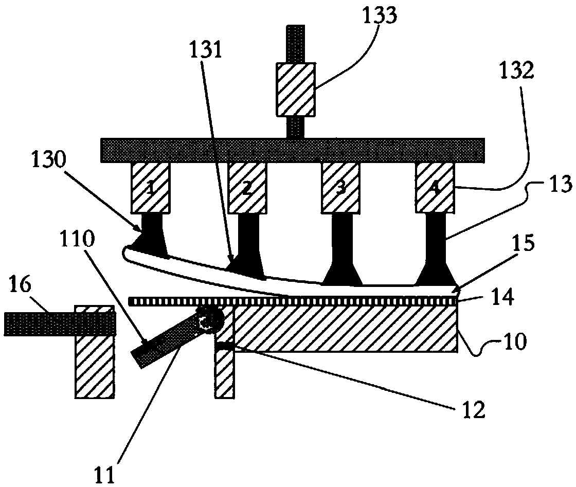
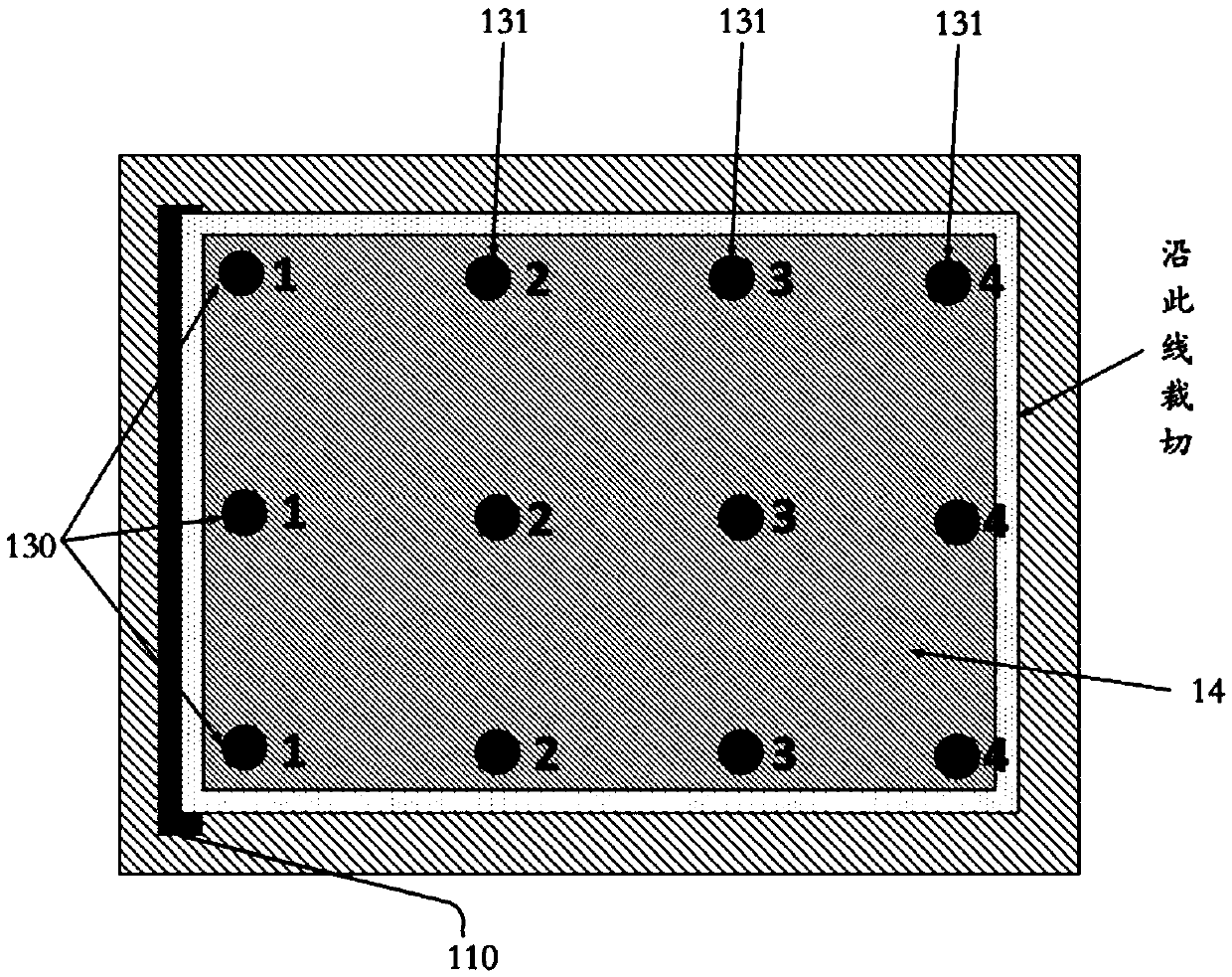
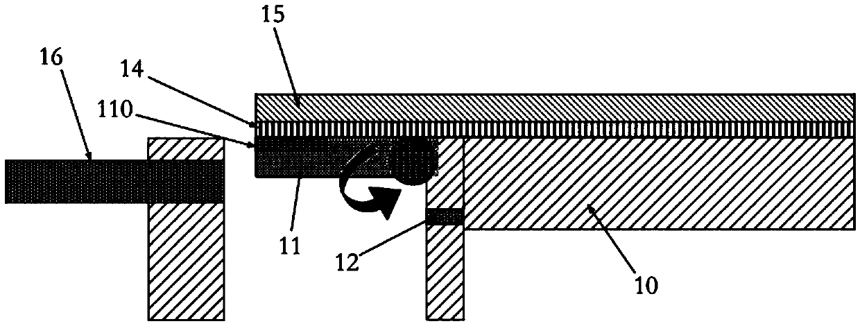
[0038] The present invention provides a display substrate peeling device for peeling a (flexible) display substrate from a (rigid) substrate, and provides its implementation. In the embodiment given by the present invention, such as figure 1 As shown, the peeling device of the display substrate includes a base 10 , a bonding plate 11 , a detection unit 12 and a separation unit 13 . The base 10 is used to place the display substrate 14; specifically, before the display substrate 14 is separated from the rigid substrate 15, the two are attached together and placed on the base 10; After peeling off, the display substrate 14 is still placed on the base 10 , and th...


PUM


Abstract

The invention provides a peeling device and a peeling method for a display substrate. The peeling device for the display substrate comprises a base board, at least one adhesive plate, a detection unit and a separation unit, wherein each adhesive plate is arranged in a region, which corresponds to the corner or edge of the display substrate, of the base board, and is connected with the base board in a rotatable manner, so that the upper surface of each adhesive plate and the upper surface of the base board are rotated in a coplanar state to the upper surface of the base board to form a non-coplanar state; the detection unit is used for detecting whether the edge region of the display substrate is adhered to the adhesive plate; the separation unit is arranged above the base board and the adhesive plate and comprises a first adsorption terminal and a second adsorption terminal which are capable of moving in the vertical direction; at least one first adsorption terminal is correspondingly arranged above the adhesive plate; a plurality of second adsorption terminals are correspondingly arranged above the base board; projections of the multiple second adsorption terminals on the base board are arranged in sequence along the region away from the corner or edge of the adhesive plate.

Description

technical field [0001] The present invention relates to display technology, especially to the field of flexible display, in particular to a device and method for peeling a (flexible) display substrate from a (rigid) substrate. Background technique [0002] The process of preparing a flexible display substrate is generally realized by relying on a rigid substrate (usually a glass substrate). The formed flexible display substrate includes a polyimide film and various signal lines and pixel electrodes formed on the polyimide film. , thin film transistors and other patterns; therefore, after the flexible display substrate is prepared, it is necessary to peel off the flexible display substrate from the rigid substrate. [0003] In the existing technical solution of separating the flexible display substrate from the glass substrate, the attached flexible display substrate and glass substrate are fixed on the base platform by vacuum adsorption (the flexible display substrate faces ...

Claims


Application Information

Patent Timeline
Patent Type & Authority Applications(China)
IPC IPC(8): G02F1/13H01L21/77B32B43/00
Inventor 王伟周翔
Owner BOE TECH GRP CO LTD
Learn More