
an exhaust device

A technology of exhaust device and exhaust valve, which is applied in the direction of valve device, valve operation/release device, separation method, etc., and can solve the problems of blocked exhaust, waste of resources, small gas collection chamber, etc.

Active Publication Date: 2018-10-16
北京德安源环境科技发展有限公司
View PDF7 Cites 0 Cited by
  • Summary
  • Abstract
  • Description
  • Claims
  • Application Information

AI Technical Summary

Problems solved by technology

[0003] 1. The air collection and exhaust chamber is too small, especially the air collection chamber is very small, which is particularly prone to the phenomenon of mixed discharge of air and water;
[0004] 2. Due to the small size of the gas-collecting chamber, the impurities in the water can easily pass through the gas-collecting chamber and cause blockage at the exhaust port, which will affect the exhaust and cause water leakage, which has caused great troubles in people's lives.
Serious leaks require uninterrupted replenishment of water, wasting resources and costing more

Method used


Image

  • an exhaust device

Examples


Embodiment Construction

[0027] The principles and features of the present invention are described below in conjunction with the accompanying drawings, and the examples given are only used to explain the present invention, and are not intended to limit the scope of the present invention.

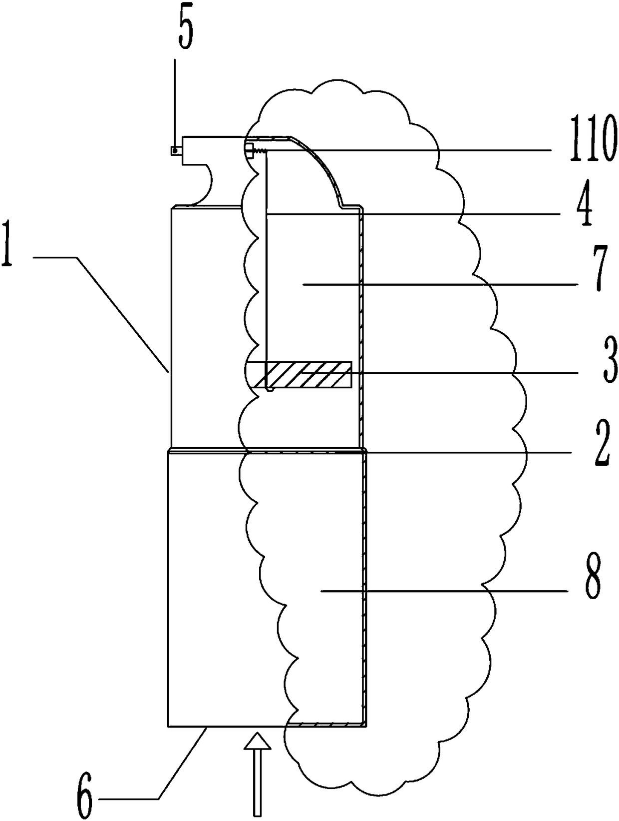
[0028] Such as figure 1 As shown, an exhaust device includes an exhaust valve 1, a filter screen 2, a float 3 and a connecting rod 4. The bottom end of the exhaust valve 1 is a gas-liquid inlet 6, and the bottom of the exhaust valve 1 is provided with There are threads for connecting with other equipment. The top of the exhaust valve 1 is an exhaust port; an exhaust valve core 110 is provided at the exhaust port of the exhaust valve 1 .

[0029] The exhaust port of the exhaust valve is a trumpet-shaped structure and is arranged horizontally. The exhaust valve core is a spherical structure connected with a spring. In a natural state, the spherical structure is located inside the horn-shaped structure and close to the...


PUM

PropertyMeasurementUnit
lengthaaaaaaaaaa

Abstract

The invention relates to an exhausting device which comprises an exhausting valve, a filter net, a floater and a connecting rod. A gas-liquid inlet is formed in the bottom end of the exhausting valve, an exhausting port is formed in the top end of the exhausting valve, an exhausting valve element is arranged at the exhausting port of the exhausting valve, the filter net is arranged inside the exhausting valve and divides the same into two areas including an exhausting cavity close to the exhausting port and a gas collection cavity close to the gas-liquid separating inlet, the connecting rod and the floater are arranged in the exhausting cavity, the top end of the connecting rod is fixedly connected with the exhausting valve element, the connecting rod moves downwards to enable the exhausting valve element to be in an open state, and a bent portion used for placement of the floater is arranged at the bottom end of the connecting rod. The exhausting device can effectively avoid gas-water mixed discharging.

Description

technical field [0001] The invention belongs to the technical field of exhaust, and in particular relates to an exhaust device. Background technique [0002] At present, the exhaust valves commonly used in water circulation systems have the following defects: [0003] 1. The air collection and exhaust chamber is too small, especially the air collection chamber is very small, which is particularly prone to the phenomenon of mixed discharge of air and water; [0004] 2. Due to the small size of the gas-collecting cavity, the impurities in the water can easily pass through the gas-collecting cavity and cause blockage at the exhaust port, which affects the exhaust and is also prone to water leakage, which has caused great troubles for people in their lives. Serious leaks require uninterrupted replenishment of water, wasting resources and costing more. Contents of the invention [0005] In view of the problems existing in the prior art, the present invention provides an exhau...

Claims


Application Information

Patent Timeline
Patent Type & Authority Patents(China)
IPC IPC(8): F16K31/20B01D35/04
CPCB01D35/04F16K31/20
Inventor 向文鉴姜涵睿
Owner 北京德安源环境科技发展有限公司
Learn More