
Method for realizing automatic screw driving and automatic screw driving machine

An automatic screw-driving machine and a technology for its implementation method, which is applied in metal processing, metal processing equipment, manufacturing tools, etc., can solve the problems of occupying working time and energy, and the improvement of overall efficiency is limited, so as to reduce labor costs, increase rework rate, high precision effect

Active Publication Date: 2016-04-20
GUANGDONG INST OF INTELLIGENT MFG +1
View PDF5 Cites 12 Cited by
  • Summary
  • Abstract
  • Description
  • Claims
  • Application Information

AI Technical Summary

Problems solved by technology

Manual screw tightening includes pure manual tightening and electric screwdriver or pneumatic screwdriver tightening. The latter generates rotational power through electric or pneumatic means to replace frequent manual tightening actions, which reduces the work of locking screws to some extent. Strength, but because manually placing the screws and aligning the screw heads still takes a lot of work time and effort, the overall efficiency improvement is relatively limited

Method used


Image

  • Method for realizing automatic screw driving and automatic screw driving machine
  • Method for realizing automatic screw driving and automatic screw driving machine

Examples


Embodiment Construction

[0043] The following will clearly and completely describe the technical solutions in the embodiments of the present invention with reference to the accompanying drawings in the embodiments of the present invention. Obviously, the described embodiments are only some, not all, embodiments of the present invention. Based on the embodiments of the present invention, all other embodiments obtained by persons of ordinary skill in the art without creative efforts fall within the protection scope of the present invention.

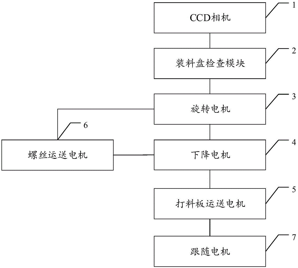
[0044] figure 1 It is a schematic flow diagram of a method for automatically driving screws in an embodiment of the present invention, as figure 1 As shown, the method includes:

[0045] S1, perform visual positioning on the knockout plate, and obtain the position of the knockout plate on the automatic screw driving machine;

[0046] S2, according to the current type of screw to be punched, check whether there is a corresponding type of screw on the charging tray...


PUM


Abstract

An embodiment of the invention discloses a method for realizing automatic screw driving and an automatic screw driving machine. The method comprises steps as follows: a knockout plate is positioned visually, and the position of the knockout plate in the automatic screw driving machine is acquired; whether a screw of the corresponding specification exists on a loading tray or not is detected; a descending motor runs to the screw taking height; a screw conveying motor conveys the screw sucked by a screwdriver bit from the position above the loading tray to the position above the knockout plate; position coordinates of a hole where the screw is to be driven in the automatic screw driving machine on the knockout plate are acquired, and the hole where the screw is to be driven on the knockout plate is conveyed to the position under the screwdriver bit; a follow motor moves to the position under the screwdriver bit driven by the screw conveying motor, and an ejection motor rises to the corresponding height according to the length of the screw; a rotating motor starts to rotate, the descending motor descends slowly, and the screw is driven into the corresponding position of the knockout plate. With the adoption of the method for realizing automatic screw driving and the automatic screw driving machine, the downward driving height of different screws can be controlled, the precision is high, the time is short, the labor cost can be reduced, the reworking rate can be decreased, and the overall efficiency can be improved.

Description

technical field [0001] The invention relates to the technical field of mechanical automation, in particular to an automatic screw-driving method and an automatic screw-driving machine. Background technique [0002] In the assembly process of home appliances, mechanical products, low-voltage electrical products, and children's toys, screw connection is the most common means. Therefore, in the assembly process of these products, screwing has become the most basic operation. In the traditional assembly process, the product is assembled by screwing the screws with a manual screwdriver. This original manual operation method requires more assembly personnel, and its labor efficiency is low, the output is low, the operation is inconsistent, and the product quality cannot be guaranteed. With the development of society and the progress of science and technology, electric screwdrivers suitable for mass production and mechanized operation have appeared. The appearance of this electric...

Claims


Application Information

Patent Timeline
IPC IPC(8): B23P19/06
CPCB23P19/001B23P19/06
Inventor 曹永军周磊何永伦林明勇
Owner GUANGDONG INST OF INTELLIGENT MFG
Learn More