Eureka AIR delivers breakthrough ideas for toughest innovation challenges, trusted by R&D personnel around the world.

Combined core-inlaid die and application method thereof

A combined mold and core insert technology, which is applied in the direction of manufacturing tools, forging/pressing/hammer devices, forging/pressing/hammering machinery, etc., can solve the problems of high manufacturing cost, difficult manufacturing, and high hardness, and achieve low manufacturing difficulty , low cost, and the effect of reducing forging costs

Inactive Publication Date: 2016-04-20
中国第二重型机械集团德阳万航模锻有限责任公司
View PDF6 Cites 4 Cited by
  • Summary
  • Abstract
  • Description
  • Claims
  • Application Information

AI Technical Summary

Problems solved by technology

Existing molds for forging titanium alloys, high-temperature alloys, ultra-high-strength steel and other materials are monolithic molds, and the molds are made of high-hardness materials such as H13. Due to their high hardness and heavy weight, manufacturing is difficult and costly

Method used


Image

  • Combined core-inlaid die and application method thereof
  • Combined core-inlaid die and application method thereof
  • Combined core-inlaid die and application method thereof

Examples


Embodiment Construction

[0036] The present invention will be further described below in conjunction with the accompanying drawings and embodiments.

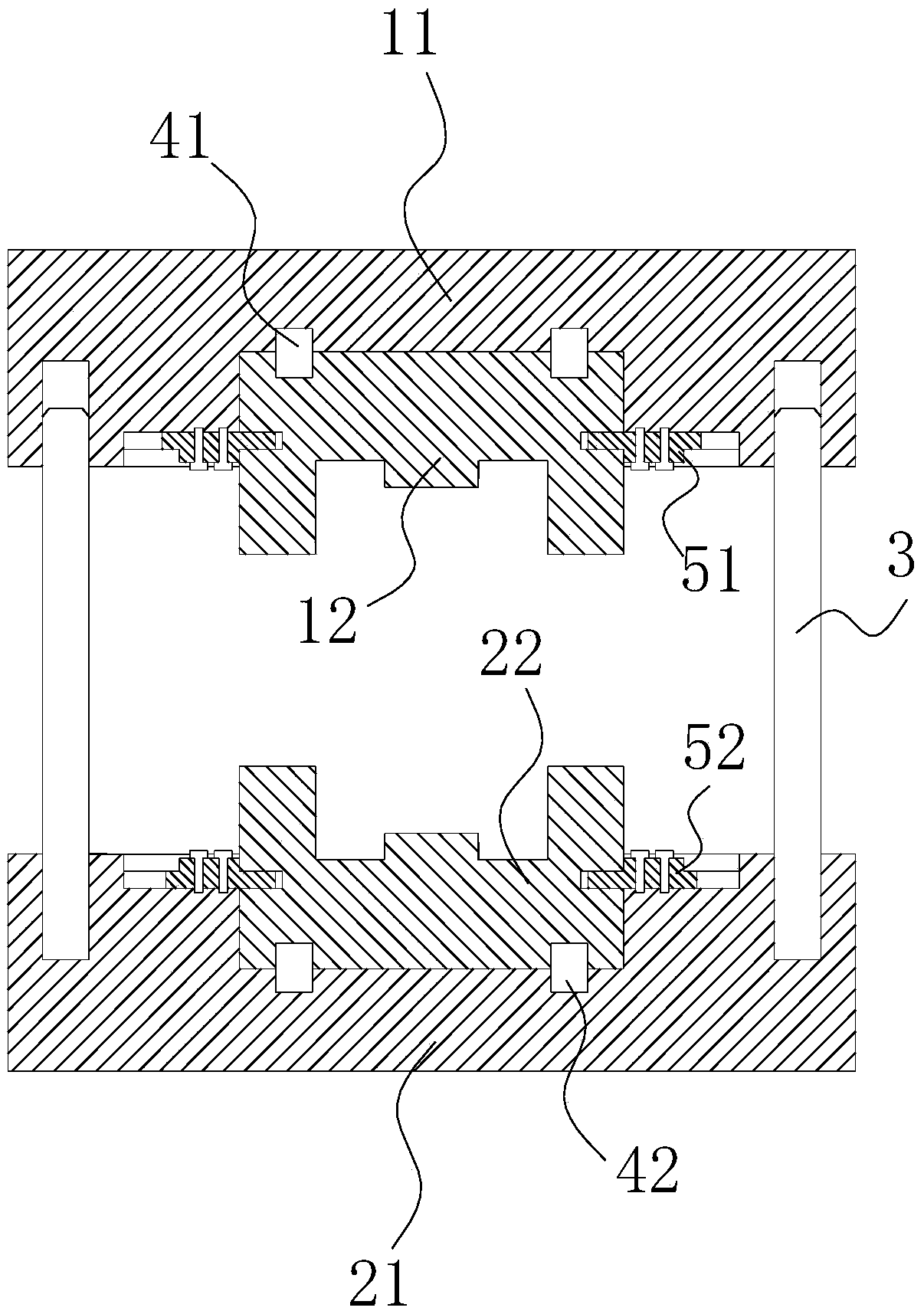
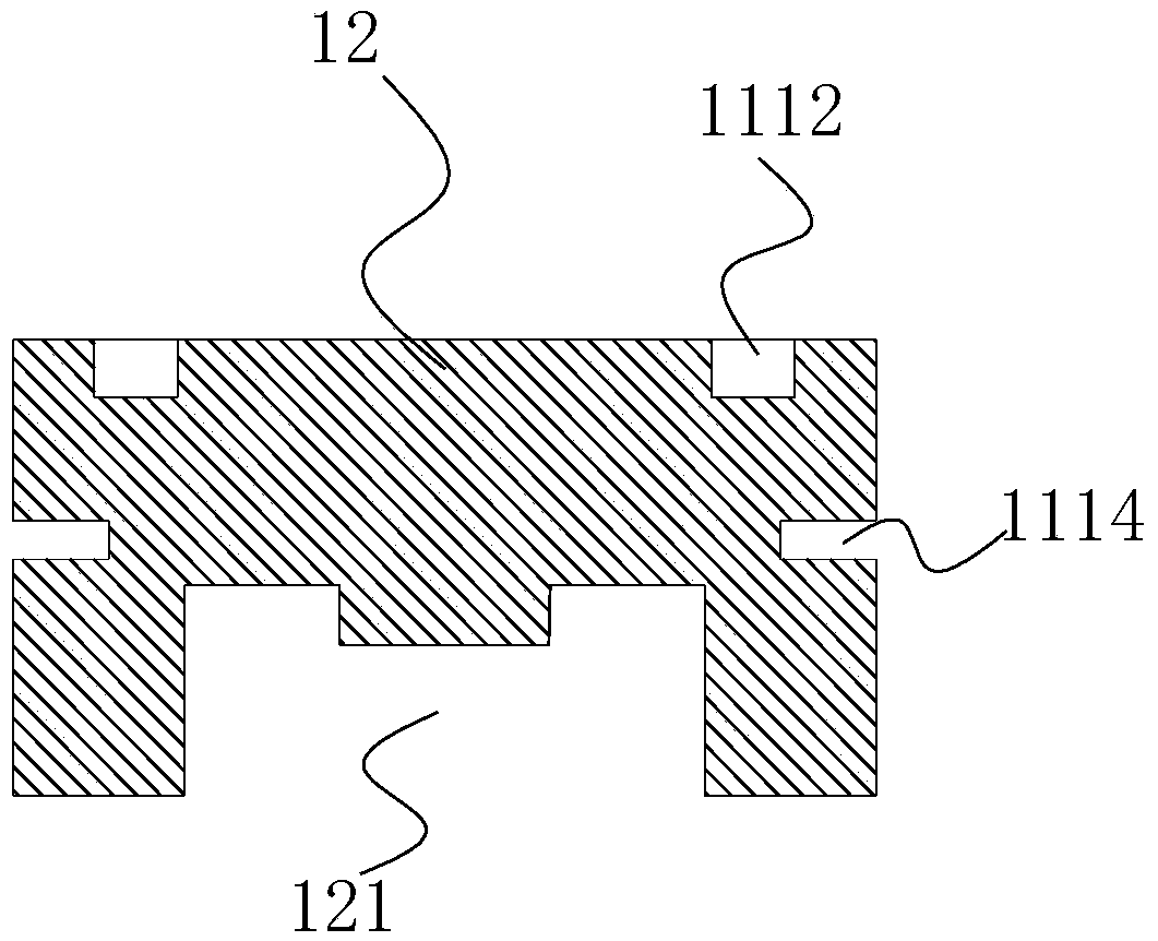
[0037] Such as figure 1 , figure 2 As shown, the core-inserted composite mold of the present invention includes a mold cover and a mold core, and the mold cover includes an upper mold cover 11 and a lower mold cover 21, and the mold core includes an upper mold core 12 and matching parts with the upper mold core 12. Lower mold core 22;

[0038] The upper mold cover 11 is provided with an upper installation groove 111, the shape and size of the outer surface of the upper mold core 12 are adapted to the shape and size of the upper installation groove 111, and the upper mold core 12 is installed in the upper installation groove 111;

[0039] The lower mold cover 21 is provided with a lower installation groove 211, the shape and size of the outer surface of the lower mold core 22 are adapted to the shape and size of the lower installation groove 211, and ...


PUM


Abstract

The invention relates to the technical field of forging, in particular to a combined core-inlaid die. The combined core-inlaid die comprises a die sleeve and a die core. The die sleeve comprises an upper die sleeve body and a lower die sleeve body. The die core comprises an upper die core body and a lower die core body. An upper mounting groove is formed in the upper die sleeve body. The upper die core body is mounted in the upper mounting groove. A lower mounting groove is formed in the lower die sleeve body. The lower die core body is mounted in the lower mounting groove. An upper die cavity is formed in the upper die core body. A lower die cavity is formed in the lower die core body. A set of guide posts are arranged between the upper die sleeve body and the lower die sleeve body. According to the combined core-inlaid die, the material cost can be reduced, and the die manufacturing difficulty can be lowered; meanwhile, the strength of the die core can meet the forging requirements, and the quality of forged pieces is not affected. An application method of the combined core-inlaid die comprises the following steps: A, selecting the corresponding upper die core body and the corresponding lower die core body according to the size of a forged piece; B, mounting the upper die core body on the upper die sleeve body, and mounting the lower die core body on the lower die sleeve body; C, mounting the guide posts; and D, conducting forging. By means of the method, the same die sleeve is applicable to die cores of various different die cavity sizes, the manufacturing quantity of dies is reduced, and the forging cost is lowered.

Description

technical field [0001] The invention relates to the technical field of forging, in particular to a core-embedded composite die and a method for using the same. Background technique [0002] The forging die is the key component to make the metal plastically deform and transmit the forging pressure. The rational design of the forging die is the basis for realizing any kind of die forging process. Die forgings of different materials and shapes have different resistances when they are formed. Die forgings of some materials are difficult to form, such as titanium alloys, high-temperature alloys, and ultra-high-strength steel. When the deformation resistance is large, the mold needs to use high-hardness materials such as H13. manufacture. Existing molds for forging titanium alloys, high-temperature alloys, ultra-high-strength steel and other materials are monolithic molds, and the entire mold is made of high-hardness materials such as H13. Due to its high hardness and heavy weigh...

Claims


Application Information

Patent Timeline
Patent Type & Authority Applications(China)
IPC IPC(8): B21J13/02B21J13/03B21J5/02
CPCB21J13/02B21J5/02B21J13/03
Inventor 张鹏王周田魏明刚孙丙金
Owner 中国第二重型机械集团德阳万航模锻有限责任公司
Why Eureka
Eureka Blog
Learn More