Magnetic field generating device for gyromagnetic bed and chair
A magnetic field generating device and magnetic bed technology, applied in electromechanical devices, using variable magnetic fields generated by mechanical movement, magnets, etc., can solve problems such as unfavorable strong magnetic field settings, insufficient optimization of magnetic field distribution, and poor magnetic health care effects. Achieve the effects of strong magnetic field, high effective utilization of magnetic field, and better magnetic health care effect
- Summary
- Abstract
- Description
- Claims
- Application Information
AI Technical Summary
Problems solved by technology
Method used
Image
Examples
Embodiment 1
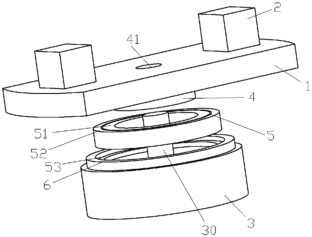
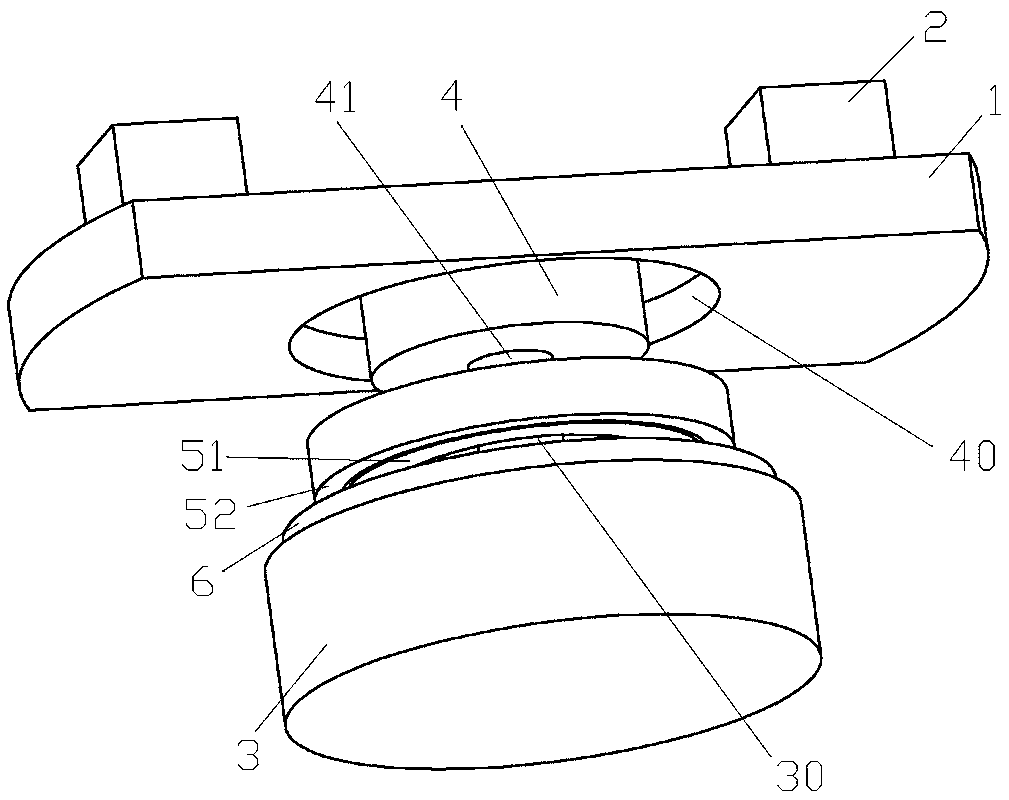
[0027] Example 1, as figure 1 , 2 As shown in the figure, a magnetic field generator for a gyromagnetic bed and a chair includes a motor 3, a motor shaft 30 of the motor 3 is extended toward the upper area of the motor 3, and a basic rotary disk 1 is assembled on the motor shaft 30. The magnetic assembly 2 is mounted on the basic rotary disk 1, and the central area of the basic rotary disk 1 forms a mounting portion 4 extending in the direction of the motor 3, and the mounting portion 4 has a mounting hole 41 through which the motor shaft 30 is passed and mounted. , the assembly part 4 is connected with an assembly carrying device. The basic rotary disk 1 is laid flat as much as possible and is preferably set so that the external shape is axisymmetric or center-symmetrical. Strong and strong magnetic pole pieces or the existing structure of several magnetic pole pieces simply superimposed, etc. In Embodiment 2, there is also an emerging combined structure of multiple...
Embodiment 2
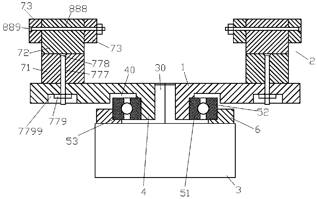
[0031] Example 2, as image 3 , 4 As shown, the difference from Embodiment 1 is: the design of the magnetic assembly 2, in this embodiment, the first solution, the magnetic assembly 2 includes a base main magnetic pole block 71 installed on the basic rotating disk 1, and the base main magnetic pole block 71 can be used alone as the magnetic assembly 2 directly, and a rectangular or cube-shaped magnetic pole block with a larger surface magnetic field intensity can be used; in the second scheme, the magnetic assembly 2 includes not only the base main magnetic pole piece 71, but also the upper main magnetic pole piece 72, The upper main magnetic pole piece 72 is arranged on the upper part of the base main magnetic pole piece 71. The upper main magnetic pole piece 72 can also be a cuboid or cube-shaped magnetic pole piece with a larger surface magnetic field intensity. The upper main magnetic pole piece 72 and the base main magnetic pole piece 71 can also be used. The size of ...
Embodiment 3
[0032] Example 3, as Figure 5 As shown, the difference between it and Embodiment 1 or 2 is that: the outer side of the magnetic assembly 2 is covered with a protective cover 8, and the lower part of the protective cover 8 extends to form a cover mounting piece 80 for fixed connection with the basic rotary disk 1. The cover mounting piece 80 can be installed and fixed with the basic rotary disk 1 through screws, etc. The protective cover 8 is a non-magnetically isolated stainless steel cover, that is, a non-magnetically isolated stainless steel cover can be used, which is not only beautiful, but also protects the magnetic pole blocks from being oxidized and avoids direct contact with ferromagnetic objects. The collision and contact with the magnetic pole block can also prevent the magnetic assembly 2 from falling off during high-speed operation and cause accidents, further optimize the structure and force distribution, improve various physical properties, and have better magn...
PUM
 Abstract
Description
Claims
Application Information
 - R&D
- Intellectual Property
- Life Sciences
- Materials
- Tech Scout
- Unparalleled Data Quality
- Higher Quality Content
- 60% Fewer Hallucinations
Browse by: Latest US Patents, China's latest patents, Technical Efficacy Thesaurus, Application Domain, Technology Topic, Popular Technical Reports.
© 2025 PatSnap. All rights reserved.Legal|Privacy policy|Modern Slavery Act Transparency Statement|Sitemap|About US| Contact US: help@patsnap.com


