
Method and system for self-tuning of encoder zero point of motor by a servo

A motor encoding and self-tuning technology, which is applied in the estimation/correction of motor parameters, control system, AC motor control, etc., can solve the problems of poor drive compatibility, reduce the universality of the drive, and increase the difficulty of the motor, etc., to achieve simple use, Reduce the requirements of system integration, reduce the installation process and the effect of difficulty

Active Publication Date: 2016-04-13
SHANGHAI STEP ELECTRIC +2
View PDF4 Cites 12 Cited by
  • Summary
  • Abstract
  • Description
  • Claims
  • Application Information

AI Technical Summary

Problems solved by technology

[0008] When the encoder is installed, it is necessary to adjust the position of the motor rotor and the zero position of the encoder to a certain relative position before it can be fixed. This has high requirements for the position accuracy of the encoder when it is fixed, and increases the process of encoder installation by the motor manufacturer. and difficulty
[0009] 2. It increases the difficulty for servo manufacturers to use motors, and reduces the versatility and seamless interchangeability of drives and motors
[0011] 3. It can only be adjusted with no load. For the installed motor with load, the zero point adjustment of the encoder cannot be completed.
For the motors already installed on the equipment, it is impossible to complete the calibration of the encoder zero point (especially for the occasions with vertical loads such as robots or lifting equipment), which increases the requirements and difficulties of system integration.
[0013] 4. Driver compatibility is poor
[0014] The motor encoder zero-point calibration of a single driver is only valid for the corresponding motor, and cannot achieve compatibility with different brands of motor encoder zero-point calibration, which reduces the versatility of the driver

Method used


Image

  • Method and system for self-tuning of encoder zero point of motor by a servo
  • Method and system for self-tuning of encoder zero point of motor by a servo
  • Method and system for self-tuning of encoder zero point of motor by a servo

Examples


Embodiment Construction

[0030] In order to make the objectives, technical solutions, and advantages of the present invention clearer, the various embodiments of the present invention will be described in detail below with reference to the accompanying drawings. However, a person of ordinary skill in the art can understand that in each embodiment of the present invention, many technical details are proposed for the reader to better understand the present application. However, even without these technical details and various changes and modifications based on the following embodiments, the technical solutions claimed by the claims of this application can be realized.

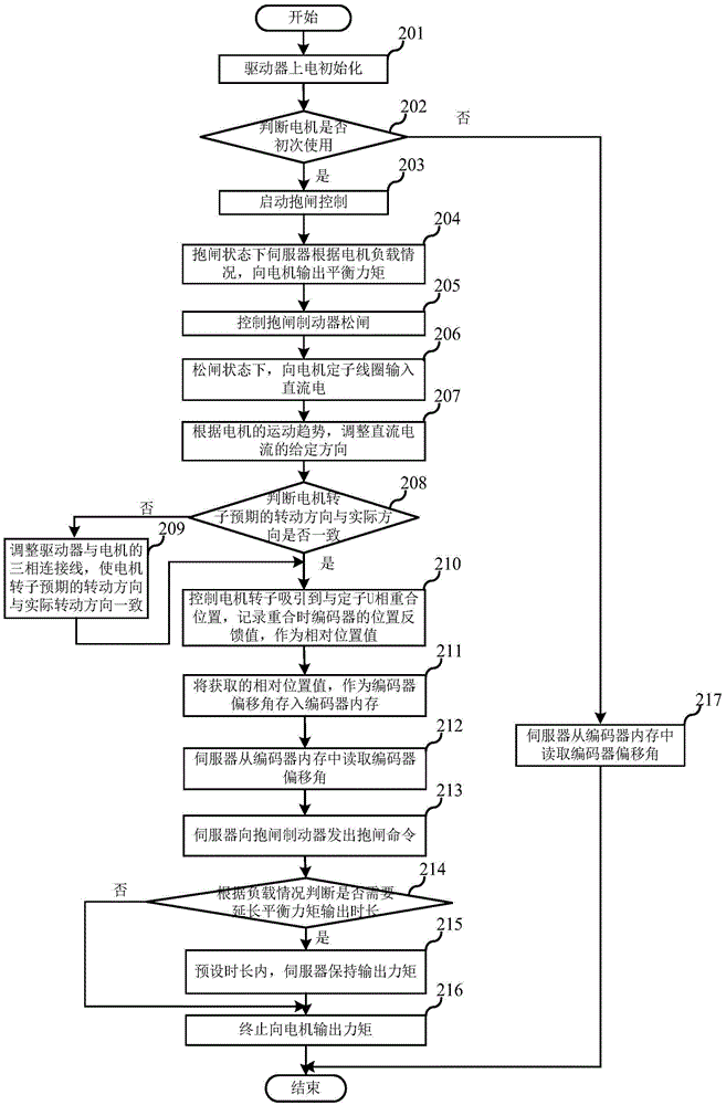
[0031] The first embodiment of the present invention relates to a method of servo self-tuning motor encoder zero point, the specific process is as follows figure 1 Shown.

[0032] In step 101, the drive is powered on and initialized.

[0033] Next, in step 102, it is determined whether the motor is used for the first time. In this embodiment,...


PUM


Abstract

The invention relates to the field of motors, and discloses a method and a system for self-tuning of an encoder zero point of a motor by a servo. The method comprises the following steps: when the motor is used for the first time, outputting a balance torque to the motor by a servo in a band-type brake state according to a load of the motor; controlling a band-type brake to be released; and outputting the torque to the motor in a brake-releasing state and obtaining relative position values of a motor rotor position and an encoder zero point position; and taking the obtained relative position values as encoder deviation angles of the motor, so that the motor can also finish correction of the encoder zero point under the condition of the load; the difficulty that a servo manufacturer utilizes the motor is lowered; the universality and the seamless interchangeability of a driver and the motor are improved; and the compatibility for setting encoder zero points with different brands by the driver is achieved.

Description

Technical field [0001] The invention relates to the field of motors, in particular to a method and system for servo self-tuning motor encoder zero point. Background technique [0002] In servo control, the encoder is a detection device for the position and speed of the motor rotor, which is essential for the closed-loop control of the servo system. Especially in FieldOrientedControl (FOC for short), the angle θ between the motor stator UVW coil and the motor rotor needs to be known at all times (usually the angle between the U phase and the motor rotor), so that the d-axis excitation component Coupling with the q-axis output component to obtain the best output effect, that is, "DC-like characteristics". This angle is usually obtained by the feedback device encoder mounted on the motor rotor. However, to accurately know the angle between the U phase of the motor stator coil and the motor rotor at a certain moment, it is necessary to know the position of the motor rotor at that t...

Claims


Application Information

Patent Timeline
Patent Type & Authority Applications(China)
IPC IPC(8): H02P23/14H02P25/02H02K11/21
CPCH02P23/14H02P25/02
Inventor 李虎修丁信忠柳竹青严彩忠王科姜宇姜荣辉
Owner SHANGHAI STEP ELECTRIC
Learn More