
Key detection circuit and key detection method of electronic equipment

A technology for detecting circuits and electronic equipment, applied in the direction of measuring electricity, measuring devices, measuring electrical variables, etc., can solve the problems of voltage detection range becoming smaller, misjudgment, and false response, etc., so as to improve accuracy and avoid misjudgment and misresponse Effect

Active Publication Date: 2018-07-13
SHENZHEN TCL DIGITAL TECH CO LTD
View PDF6 Cites 1 Cited by
  • Summary
  • Abstract
  • Description
  • Claims
  • Application Information

AI Technical Summary

Problems solved by technology

[0004] It can be seen from the above that when the number of buttons increases, the voltage range value assigned to each button becomes smaller, and the voltage detection range corresponding to each button becomes smaller, and because the power supply voltage is discrete (the power supply range of a general power supply is ±10 %, the power supply voltage offset range is -0.33~0.33V), and due to the processing of the key detection circuit, the performance of the internal components of the IC changes with temperature changes, aging and other factors, causing the key detection circuit to detect the actual value of a certain key. The voltage of a button may fall within the voltage detection range of another button, which may easily cause misjudgment and wrong response, resulting in misalignment of button functions. Therefore, in order to ensure accurate button functions, the number of buttons should not be increased too much

Method used


Image

  • Key detection circuit and key detection method of electronic equipment
  • Key detection circuit and key detection method of electronic equipment
  • Key detection circuit and key detection method of electronic equipment

Examples


Embodiment Construction

[0032] It should be understood that the specific embodiments described here are only used to explain the present invention, not to limit the present invention.

[0033] The invention provides a key detection circuit of electronic equipment.

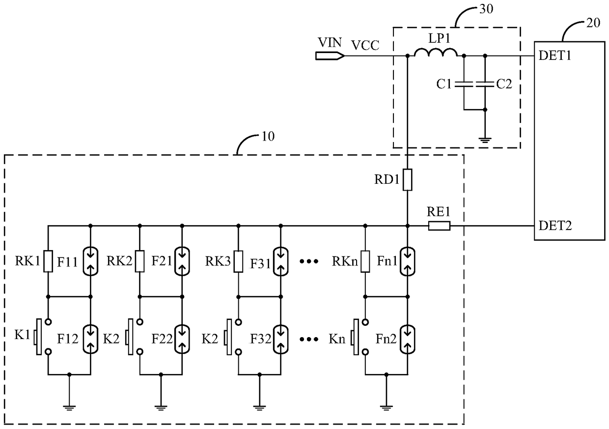
[0034] refer to figure 1 , figure 1 It is a circuit structure schematic diagram of a preferred embodiment of the key detection circuit of the electronic device of the present invention.

[0035] In a preferred embodiment of the present invention, the key detection circuit includes a power input terminal VIN, a key module 10 and a main controller 20; the input terminal of the key module 10 is connected to the power input terminal VIN, and the key module 10 The output terminal of the main controller 20 is connected to the key detection terminal DET2 of the main controller 20, and the power detection terminal DET1 of the main controller 20 is connected to the power input terminal VIN.

[0036] The main controller 20 is used to detect the ...


PUM


Abstract

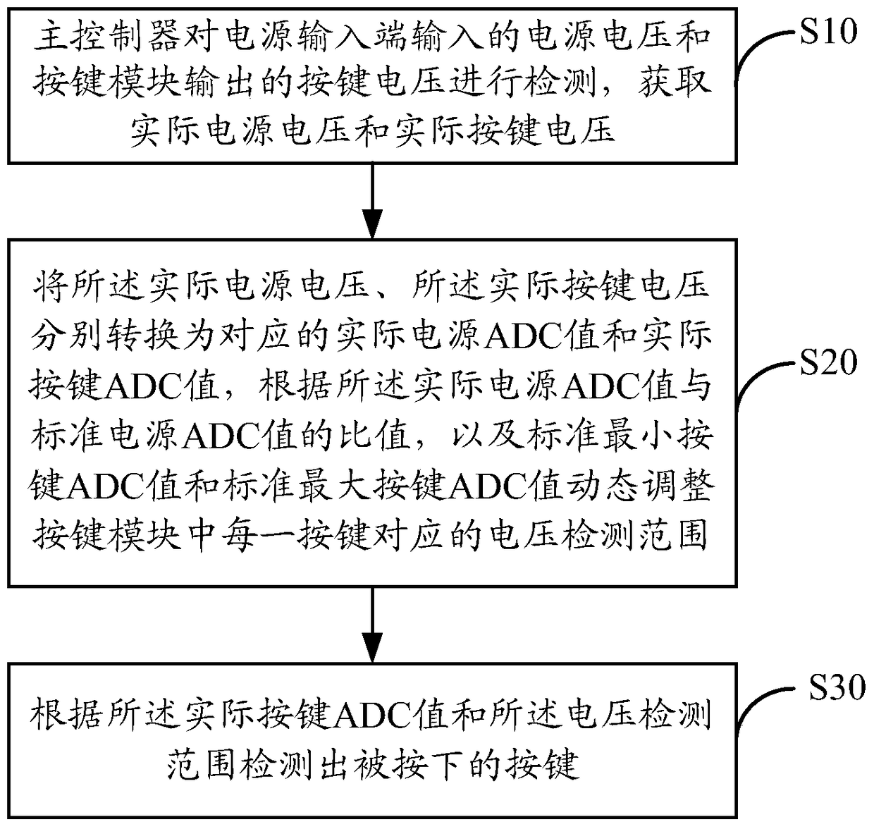
The invention discloses a key detection circuit of electronic equipment. The key detection circuit comprises a power input terminal, a key module and a main controller; the main controller detects the power supply voltage input by the power input terminal and the key voltage output by the key module, Obtain the actual power supply voltage and actual button voltage, convert the detected actual power supply voltage and actual button voltage into corresponding actual power supply ADC values ​​and actual button ADC values, according to the ratio of the actual power supply ADC value to the standard power supply ADC value, and the standard The minimum button ADC value and the standard maximum button ADC value dynamically adjust the voltage detection range corresponding to each button in the button module, and detect the pressed button according to the actual button ADC value and the voltage detection range. The invention also discloses a key detection method of the electronic equipment. The invention improves the accuracy of key detection, and can avoid misalignment of key functions caused by misjudgment and misresponse.

Description

technical field [0001] The invention relates to the technical field of key detection, in particular to a key detection circuit and a key detection method of electronic equipment. Background technique [0002] In general, for the power supply of the button module of electronic equipment, different power supplies are used in different usage occasions, which leads to the discreteness of the power supply voltage provided by the power supply to the button module, that is, the power supply voltage of the button module changes in different occasions , an offset occurs, which makes the voltage detected by the key detection circuit discrete, resulting in a key function error. [0003] In order to prevent misalignment of button functions, the method of reducing the number of buttons is generally adopted, so that each button is assigned a larger voltage range value, so as to accurately detect the button actually pressed and avoid misjudgment. For example, the power supply voltage prov...

Claims


Application Information

Patent Timeline
Patent Type & Authority Patents(China)
IPC IPC(8): G01R31/00
Inventor 宋娟王乐永张昊
Owner SHENZHEN TCL DIGITAL TECH CO LTD
Learn More