
Establishment method for topological system of video monitoring equipment and associated monitoring method

A technology of video surveillance and establishment method, which is applied in the direction of closed-circuit television system, television, electrical components, etc., to achieve the effects of saving manpower and practice, improving efficiency, improving operating efficiency and stability

Inactive Publication Date: 2016-04-06
航天科工智慧产业发展有限公司
View PDF6 Cites 12 Cited by
  • Summary
  • Abstract
  • Description
  • Claims
  • Application Information

AI Technical Summary

Problems solved by technology

[0008] The purpose of the present invention is to provide a method for establishing a video surveillance device topology system and an associated monitoring method, thereby solving the aforementioned problems in the prior art

Method used


Image

  • Establishment method for topological system of video monitoring equipment and associated monitoring method
  • Establishment method for topological system of video monitoring equipment and associated monitoring method
  • Establishment method for topological system of video monitoring equipment and associated monitoring method

Examples


Embodiment 1

[0039] Such as figure 1 with 2 As shown, the embodiment of the present invention provides a method for establishing a video surveillance device topology system, including the following steps

[0040] S1. Obtain the location information of the acquired video surveillance equipment;

[0041] S2, matching the positioning information of the video monitoring equipment with the original GIS system, generating a new GIS system including the positioning information of the video monitoring equipment, and generating the video monitoring equipment in the new GIS system topological system;

[0042] S2 includes the following steps:

[0043] S201. Obtain the location points a of all the video surveillance devices, and store the location points a in the data set A;

[0044] S202, traversing the data set A, obtaining all points p in a circle with the location point a as the center and a distance r as the radius, and storing the points p in the data set P;

[0045] S203, traversing the da...

Embodiment 2

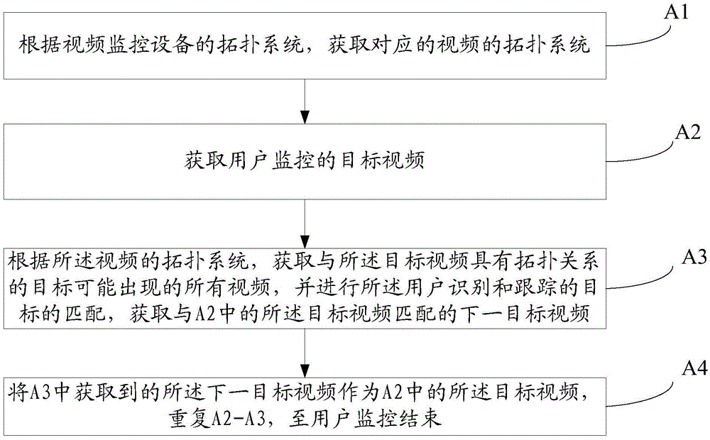
[0063] Such as image 3 As shown, the embodiment of the present invention provides a video topology correlation monitoring method, which is characterized in that it includes the following steps:

[0064] A1, using the method described in Embodiment 1 to establish the topology system of the video surveillance device, and according to the topology system of the video surveillance device, obtain the topology system of the video corresponding to the video surveillance device;

[0065] A2, obtaining the target video monitored by the user;

[0066] A3, according to the topology system of the video, obtain all videos that may appear in the target that has a topological relationship with the target video, and perform the matching of the target identified and tracked by the user, and obtain the video matching with the target in A2 the next target video of ;

[0067] A4, using the next target video acquired in A3 as the target video in A2, repeating A2-A3 until the user monitoring end...


PUM


Abstract

The invention discloses an establishment method for a topological system of video monitoring equipment and an associated monitoring method, relating to the field of video monitoring technologies. The establishment method for the topological system of the video monitoring equipment is supported by GIS (Geographic Information System) data, in comparison with a method for manually establishing the topological system in the prior art, the efficiency of the method is greatly improved, a large amount of manpower and practices are saved, and furthermore, in comparison with a method for establishing the topological system by utilizing probability estimation, machine learning and the like in the prior art, the method has no dependency on training data, the efficiency is improved, the complexity is greatly reduced, and the operating efficiency and the stability are greatly improved; and the method can be effectively utilized in the associated monitoring method provided by the embodiments of the invention, so that a large-scale multi-camera intelligent monitoring scheme is more practical.

Description

technical field [0001] The invention relates to the technical field of video monitoring, in particular to a method for establishing a video monitoring device topology system and an associated monitoring method. Background technique [0002] With the advancement of technology and the development of society, video surveillance systems have been applied in many industries, especially public security, security and other industries. They shoulder the important task of maintaining social stability and ensuring people's personal safety and property safety. Performance and functionality put forward higher requirements and expectations. [0003] Most traditional video surveillance systems use the method of capturing images from multiple surveillance devices and displaying them separately on electronic screens. Due to the relative independence and lack of relevance of the monitoring images in this way, in the field of public security applications, a large number of camera monitoring ...

Claims


Application Information

Patent Timeline
Patent Type & Authority Applications(China)
IPC IPC(8): H04N7/18
CPCH04N7/181
Inventor 白蛟蔡功房浩
Owner 航天科工智慧产业发展有限公司
Learn More