
Enlarged type elastic coupling for metal diaphragm

A technology of elastic couplings and metal diaphragms, which is applied in the direction of elastic couplings, couplings, mechanical equipment, etc., can solve the problems of large deviation and the incomplete compensation of metal diaphragm elastic couplings, and achieve the compensation effect Good, wide range of effects

Inactive Publication Date: 2016-04-06
孙翠翠
View PDF0 Cites 4 Cited by
  • Summary
  • Abstract
  • Description
  • Claims
  • Application Information

AI Technical Summary

Problems solved by technology

[0004] However, the existing metal diaphragm elastic coupling can only compensate for small axial, radial and angular deviations between the driving shaft and the driven shaft
If the deviation is large, the metal diaphragm elastic coupling cannot fully compensate

Method used


Image

  • Enlarged type elastic coupling for metal diaphragm

Examples


Embodiment Construction

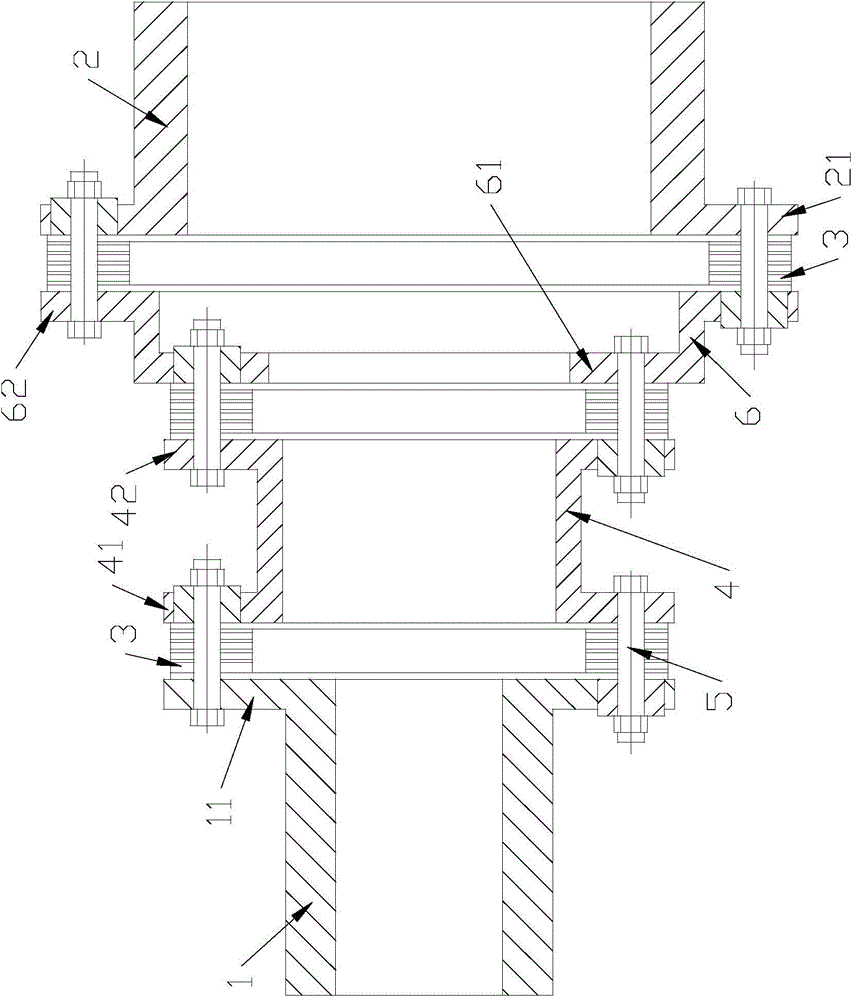
[0010] figure 1 The enlarged metal diaphragm elastic coupling shown includes an input shaft 1 with a flange 11 at one end, an output shaft 2 with a flange 21 at one end, a metal diaphragm assembly 3, and left and right ends with The first intermediate shaft 4 of the flanges 41, 42, and the second intermediate shaft 6 with flanges 61, 62 at the left and right ends respectively. The input shaft 1, the first intermediate shaft 4, the second intermediate shaft 6, and the output shaft 2 are all hollow shafts. The inner diameters of the shaft holes of the input shaft, the first intermediate shaft, and the second intermediate shaft increase sequentially, and the shaft holes of the output shaft The inner diameter is larger than the shaft bore inner diameter of the input shaft.

[0011] The flange 11 , the flange 41 and the metal diaphragm assembly 3 between the flange 11 and the flange 41 are connected by bolts 5 . The flange 41 , the flange 61 and the metal diaphragm assembly 3 bet...


PUM


Abstract

The invention provides an enlarged type elastic coupling for a metal diaphragm. According to the enlarged type elastic coupling for the metal diaphragm, the good compensation effects of the axial deviation, the radial deviation and the angular deviation between a driving shaft and a driven shaft can be played, the shaft hole inner diameter of an input shaft is not equal to that of an output shaft, the structure is simple, and the cost is low. The enlarged type elastic coupling for the metal diaphragm comprises the input shaft, the output shaft, a first intermediate shaft, a second intermediate shaft and metal diaphragm assemblies. The input shaft, the first intermediate shaft, the second intermediate shaft and the output shaft are coaxially arranged in sequence. An input shaft flange plate, a first intermediate shaft flange plate adjacent to the input shaft flange plate and the metal diaphragm assembly between the input shaft flange plate and the first intermediate shaft flange plate are all connected through bolts. The first intermediate shaft flange plate, a second intermediate shaft flange plate adjacent to the first intermediate shaft flange plate and the metal diaphragm assembly between the first intermediate shaft flange plate and the second intermediate shaft flange plate are all connected through bolts. The second intermediate shaft flange plate, an output shaft flange plate adjacent to the second intermediate shaft flange plate and the metal diaphragm assembly between the second intermediate shaft flange plate and the output shaft flange plate are all connected through bolts. The input shaft, the first intermediate shaft, the second intermediate shaft and the output shaft are all hollow shafts. The shaft hole inner diameter of the input shaft, the shaft hole inner diameter of the first intermediate shaft, and the shaft hole inner diameter of the second intermediate shaft are sequentially increased. The shaft hole inner diameter of the output shaft is larger than that of the input shaft.

Description

technical field [0001] The invention relates to a metal diaphragm elastic coupling. Background technique [0002] Metal diaphragm elastic coupling, including an input shaft with a flange at one end, an output shaft with a flange at one end, a metal diaphragm assembly, and a metal diaphragm between the flange of the input shaft and the flange of the output shaft. Diaphragm assembly; the input shaft flange, the output shaft flange and the metal diaphragm assembly between them are connected by bolts. The input shaft and the output shaft are generally hollow shafts, and key grooves are formed on the walls of the inner holes. Both the input shaft and the output shaft are hollow shafts, and the inner diameters of their shaft holes are equal. When in use, the input shaft is connected to the driving shaft through a key, and the output shaft is connected to the driven shaft through a key, so that the torque of the driving shaft is transmitted to the driven shaft. [0003] The meta...

Claims


Application Information

Patent Timeline
IPC IPC(8): F16D3/56
Inventor 孙翠翠
Owner 孙翠翠
Learn More