Caky gear clamping device

A clamping device and gear technology, applied in chucks, manipulators, program-controlled manipulators, etc., can solve the problems of inconvenient structure adjustment, reduced work efficiency, cumbersome operation process, etc., and achieve flexible structure of the grapple, convenient operation, and less The effect of small running resistance

Inactive Publication Date: 2016-04-06
CHONGQING GUANGDA MACHINERY FACTORY CO LTD
View PDF0 Cites 1 Cited by
  • Summary
  • Abstract
  • Description
  • Claims
  • Application Information

AI Technical Summary

Problems solved by technology

[0002] In order to facilitate the movement of pie-shaped gears, the existing structure uses prefabricated process holes to clamp the gears, which is very inconvenient to operate. At the same time, the structure is inconvenient to adjust, inconvenient to use, and the operation process is cumbersome, resulting in reduced work efficiency.

Method used


Image

  • Caky gear clamping device

Examples


Embodiment 1

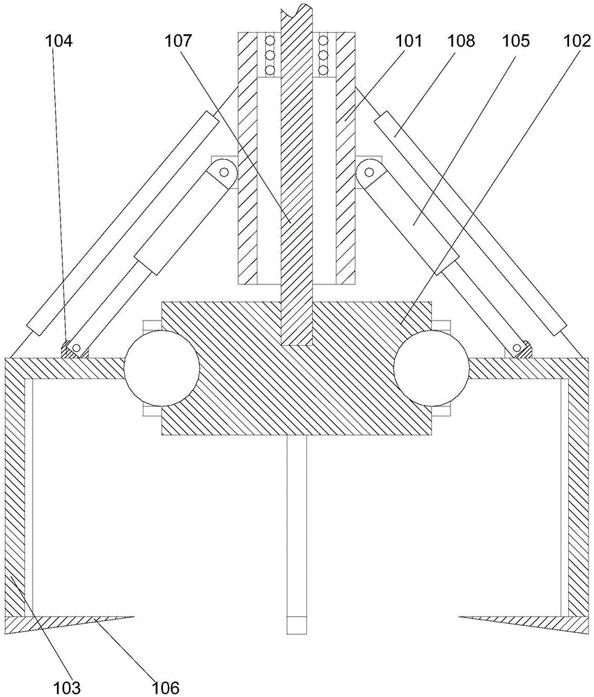
[0021] Such as figure 1 As shown, a pie-shaped gear clamping device includes a central shaft 101 and a fixed plate 102 that is arranged under the central shaft 101 and is a quadrangular prism. The grapple 103, the grapple 103 is vertically bent, one right-angled side of the grapple 103 is connected to the fixed plate 102, and the other right-angled side is around the side of the fixed plate 102, The grapples 103 are respectively connected with the spherical hinges of the fixed discs 102, flange structures 104 are respectively arranged on the upper end surfaces of the grapples 103, and four flange structures 104 are arranged on the side wall of the central axis 101 Hydraulic cylinders 105 arranged at equal intervals, one end of the four hydraulic cylinders 105 is hinged on the side wall of the central axis 101, and the other ends of the four hydraulic cylinders 105 are respectively hinged on the flange structure 104, the inside of the central axis 101 is a hollow structure, an...

Embodiment 2

[0024] In this embodiment, on the basis of Embodiment 1, in order to better fix the gear, in this embodiment, preferably, a locking portion 106 is respectively provided at the end of the grab hook 103 away from the central axis 101, so that The upper end surface of the clamping portion 106 is perpendicular to the right-angled side of the hook 103 away from the end of the central shaft 101 , and the ends of the clamping portion 106 point to the axial direction of the central shaft 101 . By providing the clamping part, the clamping part can be placed on the lower end surface of the gear, so that the clamping part can support the gear, and under the joint action of the inner wall of the grapple, the gear can be clamped conveniently.

[0025] In order to increase the relative friction between the engaging portion and the lower end surface of the gear, in this embodiment, preferably, an anti-slip emboss is provided on the upper end surface of the engaging portion 106, and the engagi...


PUM


Abstract

The invention discloses a caky gear clamping device. The caky gear clamping device comprises a center shaft and a fixing plate which is arranged below the center shaft and is a quadruple prism body. Grapnels are arranged on the four end faces of the fixing plate respectively. The grapnels are vertically bent. One right-angle sides of the grapnels are connected with the fixing plate, and the other right-angle sides of the grapnels are arranged around the side faces of the fixing plates. The grapnels are in spherically hinged connection with the fixing plate. Protruding edge structures are arranged on the upper end faces of the grapnels respectively. Four hydraulic cylinders are arranged on the side walls of the center shaft at intervals. One ends of the four hydraulic cylinders are hinged to the side walls of the center shaft, and the other ends of the four hydraulic cylinders are hinged to the protruding edge structures respectively. According to the caky gear clamping device, the four grapnel structures driven by the hydraulic cylinders are adopted for achieving clamping of a gear; meanwhile, rotary structures are adopted, and the position adjustment of the four grapnel structures can be achieved. The caky gear clamping device is simple in structure and convenient to operate.

Description

technical field [0001] The invention relates to a pie-shaped gear clamping device. Background technique [0002] In order to facilitate the movement of pie-shaped gears, the existing structure uses prefabricated process holes to clamp the gears, which is very inconvenient to operate. At the same time, the structure is inconvenient to adjust, inconvenient to use, and the operation process is cumbersome, resulting in reduced work efficiency. Contents of the invention [0003] The purpose of the present invention is to provide a pie-shaped gear clamping device, which can improve the existing problems in the prior art. By adopting four grapple structures driven by hydraulic cylinders, the clamping gear can be realized. At the same time, the rotating shaft structure can realize four The adjustment of the structural position of the grapple is simple in structure and convenient in operation. [0004] The present invention is realized through the following technical solutions: ...

Claims


Application Information

Patent Timeline
Patent Type & Authority Applications(China)
IPC IPC(8): B25J9/00B25J9/14B25J15/10
CPCB25J9/0009B25J9/14B25J15/10
Inventor 王彩虹
Owner CHONGQING GUANGDA MACHINERY FACTORY CO LTD
Why Eureka
Try Eureka