
Machining equipment

A technology for processing equipment and workbenches, applied in metal processing equipment, drilling/drilling equipment, metal processing machinery parts, etc. The effect of clamping positioning time, improving work efficiency and convenient chip removal

Inactive Publication Date: 2016-04-06
天津市蓟县华旭工贸有限公司
View PDF0 Cites 2 Cited by
  • Summary
  • Abstract
  • Description
  • Claims
  • Application Information

AI Technical Summary

Problems solved by technology

[0002] One of the chassis parts of track shoe construction machinery is a vulnerable part of the construction machinery used. Now it is commonly used on excavators, bulldozers, crawler cranes, paver and other construction machinery. The process of track shoe processing is milling The two sides of the part are required to be parallel and the size meets the tolerance requirements of the drawings, and the two processed sides and the inner cavity blank are required to have uniform wall thickness. At present, the processing of this part is completed on the CNC machine tool with automatic fixtures, and the equipment cost is relatively high. The processing cost is high, but the production efficiency is low, especially in the process of through-hole processing, once the processing is completed, the tool wears quickly, which increases the production cost and reduces the processing accuracy, thus affecting the qualified rate of the product

Method used


Image

  • Machining equipment
  • Machining equipment
  • Machining equipment

Examples


Embodiment Construction

[0020] It should be noted that, in the case of no conflict, the embodiments of the present invention and the features in the embodiments can be combined with each other.

[0021] In describing the present invention, it should be understood that the terms "center", "longitudinal", "transverse", "upper", "lower", "front", "rear", "left", "right", The orientations or positional relationships indicated by "vertical", "horizontal", "top", "bottom", "inner", "outer", etc. are based on the orientation or positional relationships shown in the drawings, and are only for the convenience of describing the present invention Creation and simplification of description, rather than indicating or implying that the device or element referred to must have a specific orientation, be constructed and operate in a specific orientation, and therefore should not be construed as limiting the invention. In addition, the terms "first", "second", etc. are used for descriptive purposes only, and should no...


PUM


Abstract

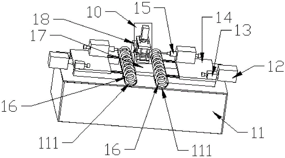
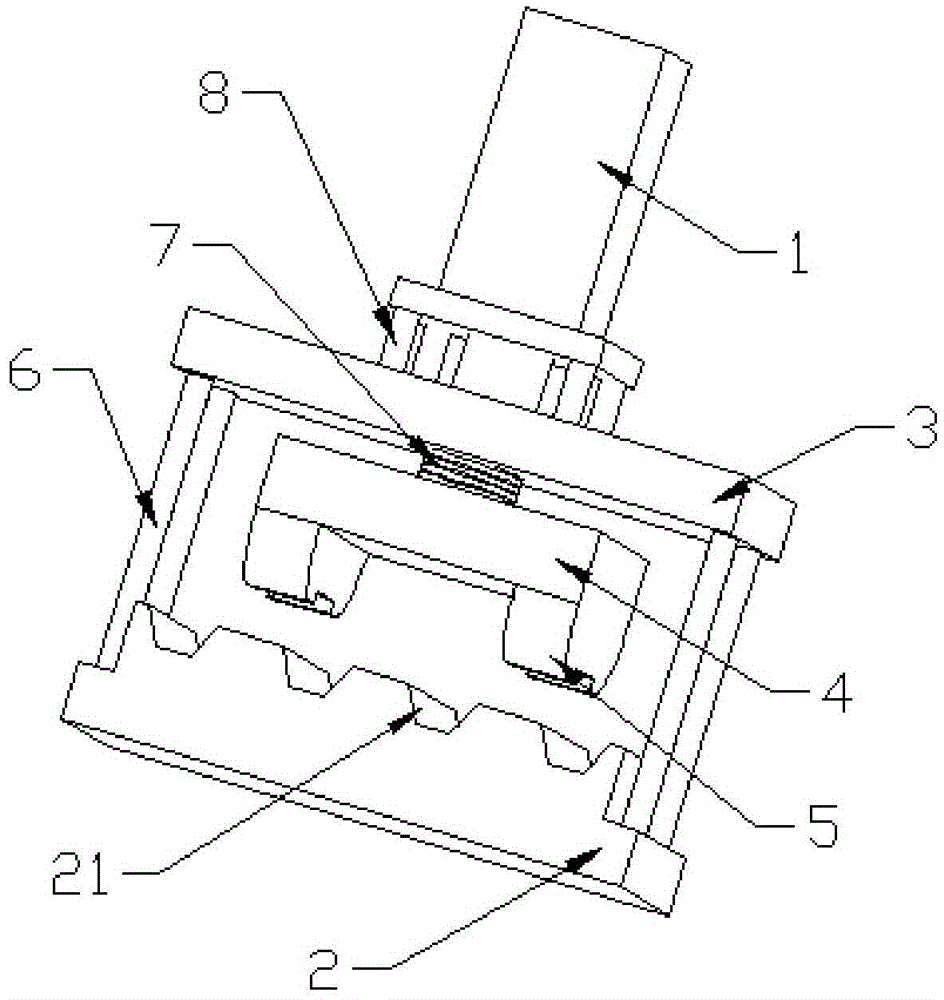
The invention provides machining equipment. The machining equipment comprises a worktable, two cutters, two machining tables, two X-axis motors, two drive motors and a work-piece clamping assembly; the work-piece clamping assembly is arranged at one end above the worktable in a centered mode and is connected to the worktable in a sliding mode through a nut and a screw mechanism; the two cutters, the two machining tables, the two X-axis motors and the two drive motors are used in a paired mode and are symmetrically arranged relative to the work-piece clamping assembly; according to the structure on one side, the drive motors drive the cutters to rotate through a belt, the drive motors and the cutters are fixed to the machining tables, and the X-axis motors drive the machining tables to be connected to the worktable in a sliding mode through the nut and the screw mechanism. According to the machining equipment, the symmetrical structure is adopted, the two sides of a work-piece can be machined simultaneously, and therefore the work efficiency is improved; the movement in the X-axis direction and the Y-axis direction can be realized, and therefore the machining range is expanded.

Description

technical field [0001] The invention belongs to the field of mechanical processing equipment, and in particular relates to a processing equipment. Background technique [0002] One of the chassis parts of track shoe construction machinery is a vulnerable part of the construction machinery used. Now it is commonly used on excavators, bulldozers, crawler cranes, paver and other construction machinery. The process of track shoe processing is milling The two sides of the part are required to be parallel and the size meets the tolerance requirements of the drawings, and the two processed sides and the inner cavity blank are required to have uniform wall thickness. At present, the processing of this part is completed on the CNC machine tool with automatic fixtures, and the equipment cost is high. The processing cost is high, but the production efficiency is low, especially in the process of through-hole processing, once the processing is completed, the tool wears quickly, which in...

Claims


Application Information

Patent Timeline
Patent Type & Authority Applications(China)
IPC IPC(8): B23B41/00B23B47/20B23Q3/08B23Q11/00
CPCB23B41/00B23Q3/082B23Q5/402B23Q11/0042
Inventor 李长江
Owner 天津市蓟县华旭工贸有限公司
Learn More