Ammonia gas absorption device

A technology of absorption device and tail gas absorption tower, which is applied in gas treatment, dispersed particle separation, membrane technology and other directions, can solve problems such as affecting the dissolution and recovery of ammonia gas, causing pollution to the environment, and difficult to fill fog droplets, etc., to achieve great social benefits, The effect of low operating cost and simple operation

Inactive Publication Date: 2016-04-06
TIANJIN HANDEWEI PHARMA
View PDF0 Cites 9 Cited by
  • Summary
  • Abstract
  • Description
  • Claims
  • Application Information

AI Technical Summary

Problems solved by technology

[0002] The large amount of ammonia gas produced by the hydrolysis of raw materials in the process of hydrolyzing nicotinic acid and isonicotinic acid in the industry will pollute the environment if it is directly discharged; after being treated by a wastewater treatment device or regulated with acidic substances, the amount of treated wastewater is large and requires Benefits can only be generated after purification and reprocessing, the recovery cost is high and the process is complicated
In the existing ammonia treatment or recovery devices, most of them adopt the method of spraying liquid in the absorption tower to dissolve the ammonia gas in the sprayed mist liquid, and use multi-stage absorption tanks equipped with cooling equipment for cyclic absorption. However, Because the gas is in a flowing state in the container, it is difficult for the sprayed mist to fill the entire container, that is, there is a dead angle in the container that is difficult for the mist to reach, which affects the dissolution and recovery of ammonia gas.

Method used


Image

  • Ammonia gas absorption device

Examples


Embodiment Construction

[0016] It should be noted that, in the case of no conflict, the embodiments of the present invention and the features in the embodiments can be combined with each other.

[0017] Specific embodiments of the present invention will be described in detail below in conjunction with the accompanying drawings.

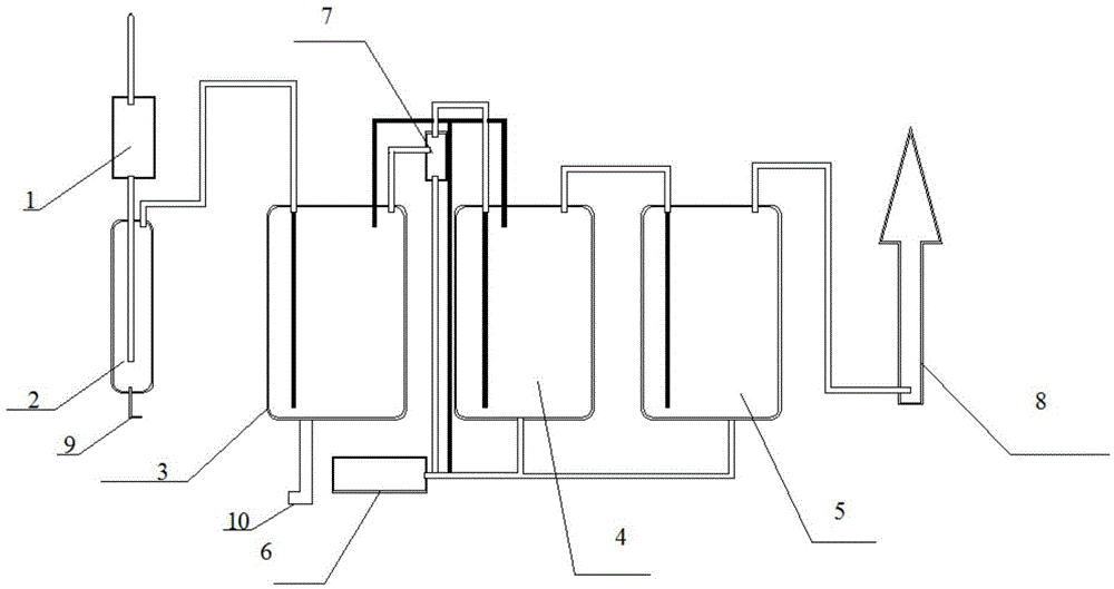
[0018] like figure 1 Shown, a kind of ammonia absorption device comprises condenser 1, buffer tank 2, primary absorption tank 3, secondary absorption tank 4, tertiary absorption tank 5 and tail gas absorption tower 8; condenser 1, buffer tank 2, The first-level absorption tank 3, the second-level absorption tank 4, the third-level absorption tank 5 and the tail gas absorption tower 8 are connected in sequence through gas pipelines; Wrapped with an insulating layer, there are cooling devices inside the primary absorption tank 3 and the secondary absorption tank 4 .

[0019] The above-mentioned primary absorption tank 3, secondary absorption tank 4 and tertiary absorption ta...


PUM


Abstract

The invention provides an ammonia gas absorption device. The device comprises a condenser, a buffer tank, a first-grade absorption tank, a second-grade absorption tank, a third-grade absorption tank and a tail gas absorption tower; the condenser, the buffer tank, the first-grade absorption tank, the second-grade absorption tank, the third-grade absorption tank and the tail gas absorption tower are sequentially connected through gas transmission pipelines; the outer side wall of the first-grade absorption tank and the outer side wall of the second-grade absorption tank are each wrapped with an insulating layer, and cooling devices are arranged inside the first-grade absorption tank and the second-grade absorption tank respectively. According to the ammonia gas absorption device, coil pipes which contain cooling water are arranged in the absorption tanks, and the insulating layers are arranged outside tank bodies, so that the temperature is maintained at 25 DEG C and below, and the ammonia gas absorption rate can reach 99% and above only through water absorption; operation is simple, and operating cost is quite low; through circulatory absorption of the first-grade absorption tank, the second-grade absorption tank and the third-grade absorption tank, generated ammonia water can be reutilized, the yield can reach 99% and above, influence on the environment is eliminated, and great social benefits are achieved.

Description

technical field [0001] The invention belongs to the field of chemical equipment, and in particular relates to an ammonia absorption device. Background technique [0002] A large amount of ammonia gas produced by the hydrolysis of raw materials in the process of hydrolyzing nicotinic acid and isonicotinic acid in the industry will pollute the environment if it is directly discharged; after being treated by a wastewater treatment device or regulated with acidic substances, the amount of treated wastewater is large and requires Only after purification and reprocessing can it produce benefits, and the recovery cost is high and the process is complicated. In the existing ammonia treatment or recovery devices, most of them adopt the method of spraying liquid in the absorption tower to dissolve the ammonia gas in the sprayed mist liquid, and use multi-stage absorption tanks equipped with cooling equipment for cyclic absorption. However, Because the gas is in a flowing state in the...

Claims


Application Information

Patent Timeline
IPC IPC(8): B01D53/18
CPCB01D53/18B01D2257/406
Inventor 王立峰
Owner TIANJIN HANDEWEI PHARMA
Why Eureka
Try Eureka