
Spiral lifting stirrer, cup lid and cup

A technology of spiral lifting and agitator, applied in the field of mixing equipment, can solve the problems of heavy overall mass, uneven mixing, complex structure, etc., and achieve the effect of easy cleaning, convenient operation and simple structure

Inactive Publication Date: 2016-04-06
SICHUAN JIUDINGZHIYUAN INTPROP OPERATIONS CO LTD
View PDF5 Cites 8 Cited by
  • Summary
  • Abstract
  • Description
  • Claims
  • Application Information

AI Technical Summary

Problems solved by technology

[0002] The stirring device in the current technology generally uses manual rotation to draw a circle for stirring, or the electric motor is used to drive the stirring device to stir, and manual stirring will cause uneven stirring, and it is necessary to have a stirring device outside. Although electric stirring can overcome The problem of uneven stirring, but its structure is complex and the overall quality is very heavy. It is obviously very unrealistic to apply it to some portable items. For example, when mixing some solutions in a water cup, how can it be stirred evenly, and the stirring device is very simple and portable , is a very urgent question before us

Method used


Image

  • Spiral lifting stirrer, cup lid and cup
  • Spiral lifting stirrer, cup lid and cup
  • Spiral lifting stirrer, cup lid and cup

Examples


Embodiment 1

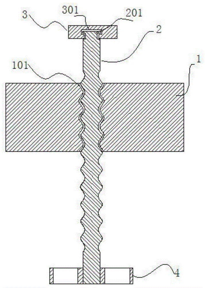
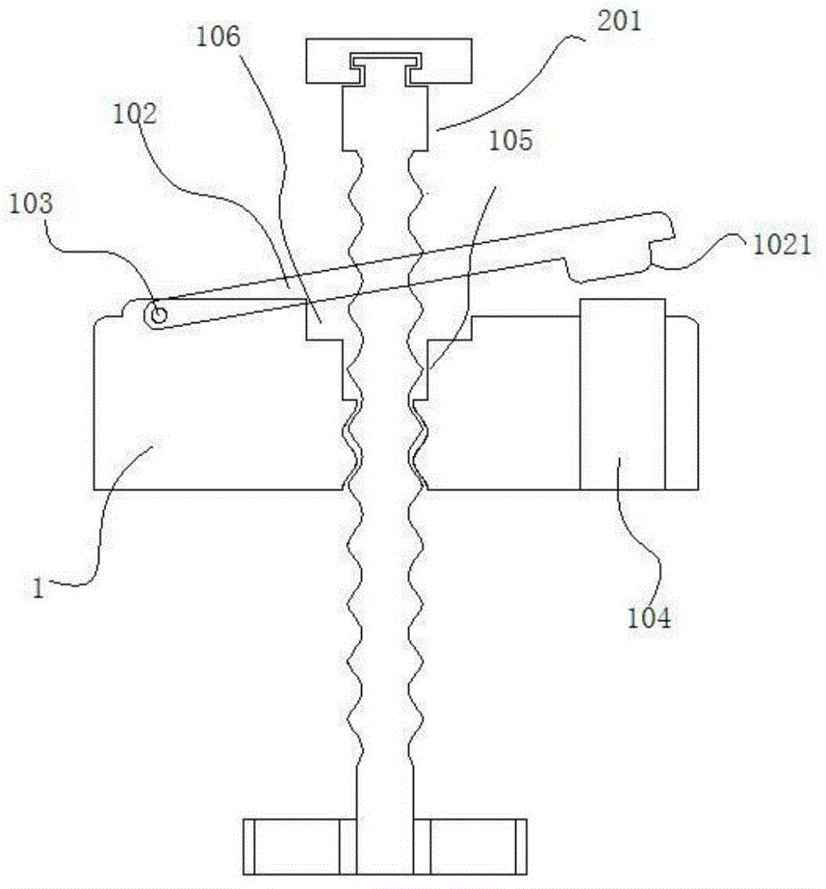
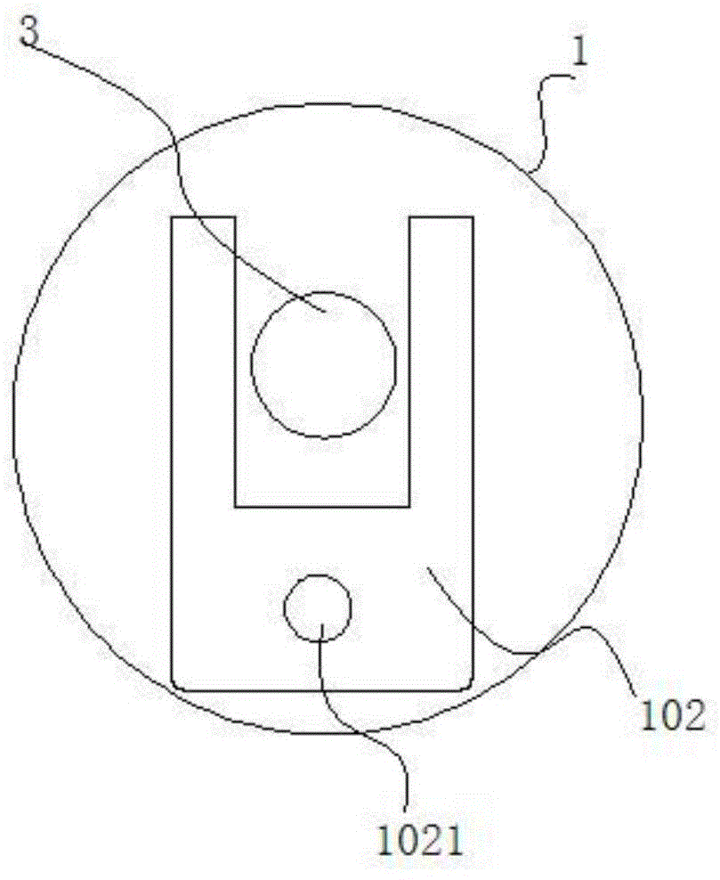
[0023] Example 1: figure 1 It shows an embodiment of a spiral lift agitator of the present invention, a spiral lift stirrer, including a main cover plate 1, a screw shaft 2, a gripping part 3 and a stirring device 4, the middle part of the main cover plate 1 is provided with a spiral Guide hole 101, the spiral guide hole 101 is pierced with a matching screw shaft 2, the upper part of the screw shaft 2 is connected with a relatively rotatable grip part 3, and the lower part of the screw shaft 2 is provided with a stirring device 4, This kind of setting fixes the main cover, hold the grip part by hand, and move it up and down, so that the screw shaft rotates in the screw guide hole, and the screw shaft and the grip part can rotate, so the up and down motion is converted into rotation movement, so as to drive the stirring device to rotate to achieve the purpose of stirring, and the vertical position of the stirring device can be changed to make the stirring more uniform. A groov...

Embodiment 2

[0024] Embodiment 2: the embodiment of a spiral lift agitator of the present invention is not shown in the figure. The difference between it and Embodiment 1 is that a bearing is provided at the connection between the spiral shaft 2 and the gripping part 3, and the spiral The shaft 2 and the inner ring of the bearing, the grip part 3 and the outer ring of the bearing are all interference fits. This connection method makes the rotation between the two parts more stable and enables them to be connected as a whole in the vertical direction. .

Embodiment 3

[0025] Embodiment 3: An embodiment of a cup cover with a spiral lift agitator is not shown in the figure, and a spiral lift stirrer according to Embodiment 1 or 2 is used, and the main cover plate 1 of the spiral lift stirrer is embedded as a whole Inside the cup cover, the screw shaft 2 passes through the cup cover and can rotate relative to the cup cover. In this way, without changing the overall structure of the cup, it is only necessary to embed the entire stirrer in the cup cover, or it can be used for active stirring Device, one stirring device corresponds to multiple containers to be stirred.


PUM


Abstract

The invention discloses a spiral lifting stirrer. The spiral lifting stirrer comprises a main cover plate (1), a spiral shaft (2), a holding part (3) and a stirring device (4), a spiral guide hole (101) is formed in the middle of the main cover plate (1), the spiral shaft (2) matched with the spiral guide hole (101) is arranged in the spiral guide hole (101) in a penetrating mode, the holding part (3) capable of relatively rotating is connected to the upper portion of the spiral shaft (2), and the stirring device (4) is arranged on the lower portion of the spiral shaft (2). The spiral lifting stirrer is simple in structure, convenient to operate, capable of achieving even stirring and easy to clean, the stirring device and a cup form an integral structure, the stirring device does not need to be additionally equipped, and the function of stirring at any moment can be achieved according to needs.

Description

technical field [0001] The invention belongs to the field of stirring equipment, in particular to a spiral lifting stirrer, a cup cover and a cup using the stirrer. Background technique [0002] The stirring device in the current technology generally uses manual rotation to draw a circle for stirring, or the electric motor is used to drive the stirring device to stir, and manual stirring will cause uneven stirring, and it is necessary to have a stirring device outside. Although electric stirring can overcome The problem of uneven stirring, but its structure is complex and the overall quality is very heavy. It is obviously very unrealistic to apply it to some portable items. For example, when mixing some solutions in a water cup, how can it be stirred evenly, and the stirring device is very simple and portable , is a very urgent question before us. Contents of the invention [0003] The object of the present invention is to: propose a kind of spiral lift stirrer and the cu...

Claims


Application Information

Patent Timeline
Patent Type & Authority Applications(China)
IPC IPC(8): A47J43/07A47G19/22
Inventor 卢晔
Owner SICHUAN JIUDINGZHIYUAN INTPROP OPERATIONS CO LTD
Learn More