
Micro-cultivator

A micro tillage machine and frame technology, applied in the field of micro tillage machines, can solve the problems that the armrest frame cannot be rotated and adjusted, the micro tillage machine has a large dead angle of cultivation, and does not have a shock absorbing mechanism, so as to eliminate the difficulty of steering, eliminate the dead angle of cultivation, Rotate to adjust the effect conveniently

Inactive Publication Date: 2016-04-06
CHONGQING SHINERAY AGRI MACHINERY
View PDF6 Cites 1 Cited by
  • Summary
  • Abstract
  • Description
  • Claims
  • Application Information

AI Technical Summary

Problems solved by technology

[0005] In view of this, the purpose of the present invention is to provide a micro tillage machine to solve the technical problems that the existing micro tillage machine armrest frame cannot be rotated and adjusted, resulting in a large dead angle of cultivation and difficult turning in the micro tillage machine; The existing crawler walking mechanism does not have a shock-absorbing mechanism, and the micro-cultivator has a technical problem of large vibration and laborious operation when walking.

Method used


Image

  • Micro-cultivator
  • Micro-cultivator
  • Micro-cultivator

Examples


Embodiment Construction

[0020] The present invention will be further described below in conjunction with the accompanying drawings and embodiments.

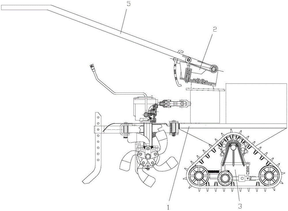
[0021] As shown in the figure, this embodiment includes a frame 1 on which a handrail frame device 2 and a crawler belt running mechanism 3 are arranged;

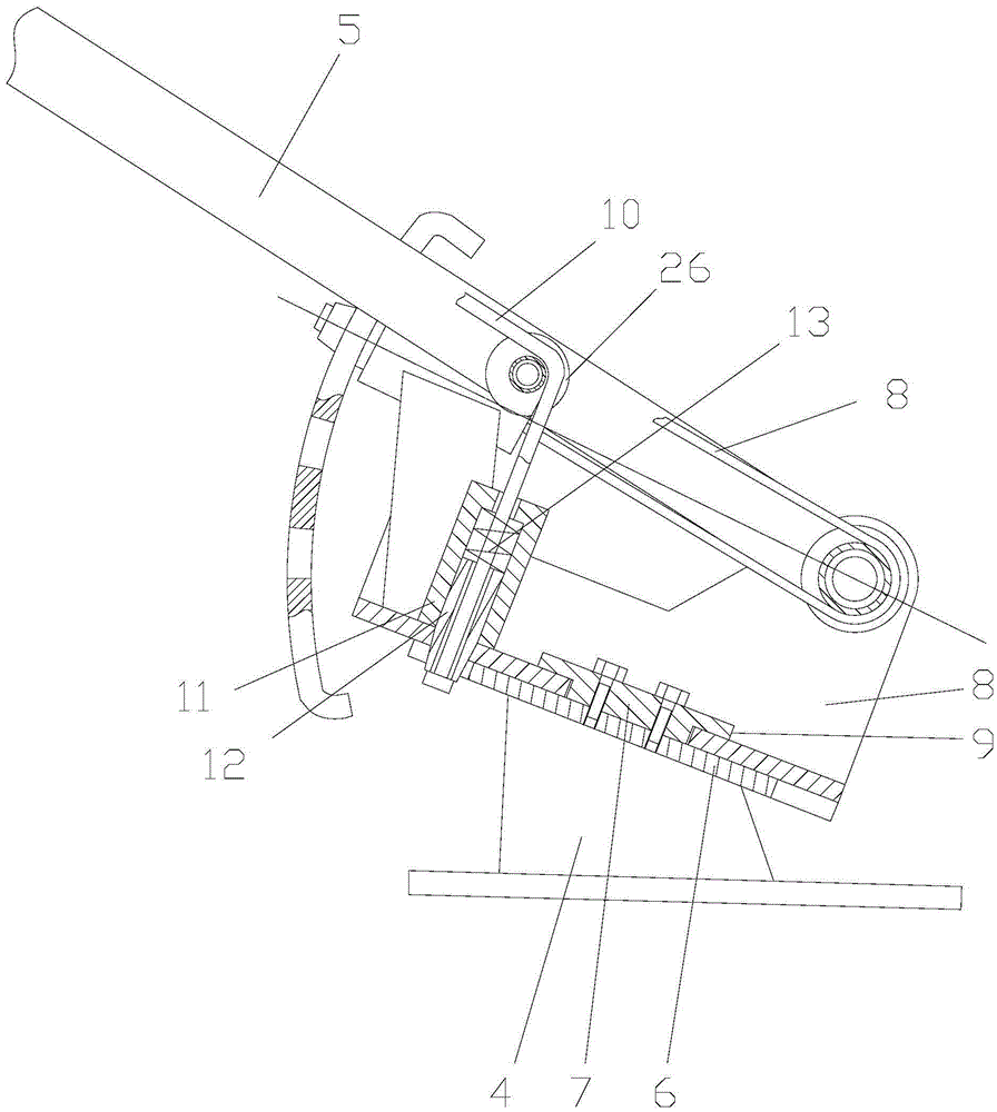
[0022] The armrest frame device includes a support 4 and an armrest frame 5, the support is fixedly connected with a rotating positioning disc 6, and the rotating positioning disc is fixedly connected with a positioning shaft 7 by screws, and the positioning shaft is covered with a rotating shaft 7 that is matched with its rotation. Seat 8, the upper end of the positioning shaft is also provided with an annular flange 9 to prevent the rotating seat from coming out in the axial direction;

[0023] The armrest frame device also includes a latch device and an adjustment cable 10, the latch device includes a latch sleeve 11 vertically fixedly connected to the swivel base, a latch 12 slidingly fitted with...


PUM


Abstract

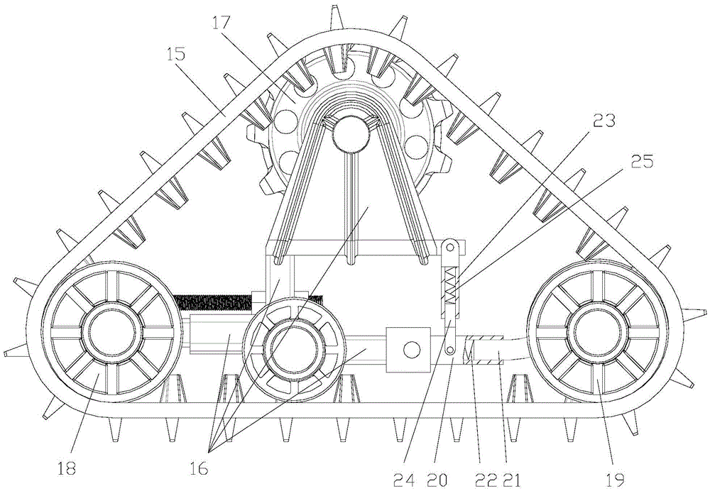
The invention discloses a micro-cultivator. The micro-cultivator comprises a rack, a handle device and a crawler belt walking mechanism. The handle device comprises a rotation positioning disk, a positioning shaft, a rotation seat, a bolt device and an adjusting stay cable. The crawler belt walking mechanism comprises a crawler belt, a walking support and a damping device. According to the invention, when a handle requires to be rotated, a bolt is pulled through the adjusting stay cable, the end portion of the bolt draws back to a bolt sleeve from a bolt positioning hole in the rotation positioning disk, then the handle can be driven to rotate around the positioning shaft, the rotation adjustment is convenient, and technical problems that a fixed handle causes large cultivation blind angles and is difficult to steer are solved. When the micro-cultivator walks and when a guiding wheel at the front end in the walking direction is in contact with a bulged portion on the ground, the guiding wheel gets a transverse impact force, then a horizontal damping spring can be compressed by a horizontal slide bar connected to the guiding wheel, and the horizontal damping spring absorbs the impact energy so as to reduce the vibration, so that the vibration generated when the micro-cultivator walks can be reduced, and the operation for the micro-cultivator saves more labor.

Description

technical field [0001] The invention relates to a tillage machine, in particular to a tiller. Background technique [0002] Tillers are powered by small diesel engines or gasoline engines, and have the characteristics of light weight, small size, and simple structure. Tillers are widely used in dry land, paddy fields, orchards, etc. in plains, mountains, and hills. Equipped with corresponding equipment, it can be used for pumping, power generation, spraying, spraying and other operations, and can also be towed for short-distance transportation. The tiller can be used freely in the field, which is convenient for users to use and store, eliminating the need for large-scale agricultural machinery to enter The troubles of mountainous fields are the best choice for farmers and consumers to replace cattle plowing. [0003] In the prior art, the armrest frame of the micro tillage machine is a fixed structure, which cannot be adjusted in the circumferential direction. Since the ar...

Claims


Application Information

Patent Timeline
IPC IPC(8): A01B33/02A01B69/06A01B71/06
CPCA01B33/02A01B69/007A01B71/06
Inventor 刘樑刘新胜窦思勇
Owner CHONGQING SHINERAY AGRI MACHINERY
Learn More