
Spindle unit

A spindle and rotor technology, applied in the field of spindle units, can solve problems such as lack of equipment, and achieve the effects of low production cost, compact design, and convenient maintenance

Inactive Publication Date: 2017-09-26
徐伟腾
View PDF4 Cites 0 Cited by
  • Summary
  • Abstract
  • Description
  • Claims
  • Application Information

AI Technical Summary

Problems solved by technology

[0004] Therefore, there has not been a large amount of direct production of fibers into most of the raw materials that are shaped into final products or main products according to the spring-like trajectory.

Method used


Image

  • Spindle unit
  • Spindle unit
  • Spindle unit

Examples


Embodiment approach 1

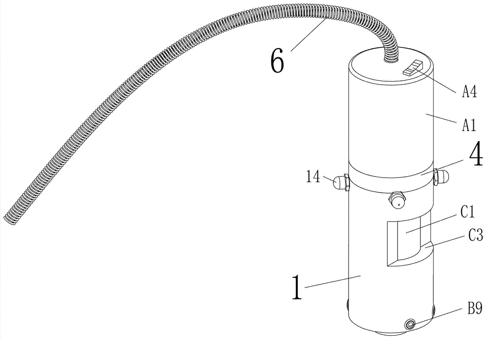
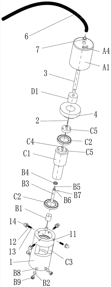
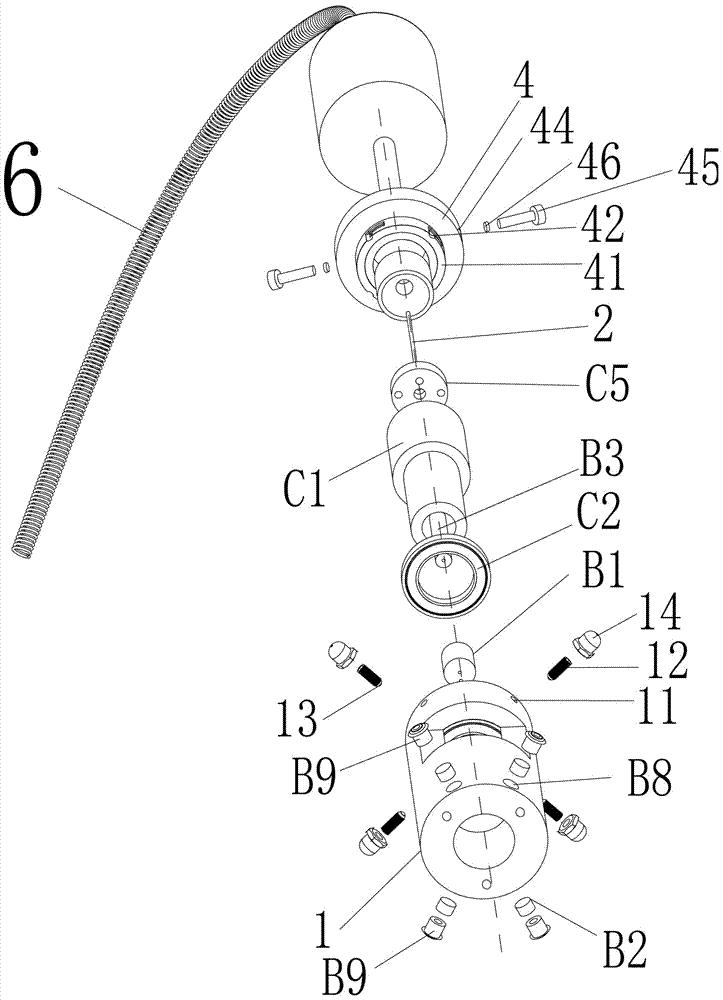
[0034] Implementation mode one, refer to Figure 1 to Figure 4 , the spindle unit is used to shape the fiber material line. Multiple spindle units can be arranged in an array to form the core part of the production equipment. The spindle unit includes a shell (1), and the inner cavity section of the shell (1) can be There are many geometric forms, but for the sake of mechanical processing, matching with other parts during use, and use efficiency, the cross section of the inner cavity is circular, and the housing (1) is equipped with a stator mechanism that is always kept non-rotating. The stator A shaft (2) is fixed on the mechanism. The cross section of the shaft (2) is circular, elliptical or polygonal. The shaft (2) runs through a rotor mechanism, and the material line passes through the feeding mechanism or the stator mechanism. The material line driven by the rotor mechanism rotates around the shaft (2), so that the material line is wound on the shaft (2) and is heated an...

Embodiment approach 2

[0055] Implementation mode two, see Figure 5 , Figure 6 , the spindle unit is used to shape the fiber material line. Multiple spindle units can be arranged in arrays and combined to form the core part of the production equipment, including a shell (1), the two ends of the shell are connected, and the side is provided with an opening (C3) ;

[0056] A cover (4) can be matched and sealed with one end of the housing (1), and a discharge hollow tube (3) is fixed in the middle of the cover (4); the discharge hollow tube (3) is covered with a heating device;

[0057] A rotor mechanism, the rotor mechanism includes a rotor (C1) with a middle penetration, the two ends of the rotor (C1) are covered with large bearings (C2), the outer shaft of the large bearing (C2) is fixed on the inner wall of the housing (1), and the rotor (C1) ) is also provided with inlet holes running through both ends;

[0058] A stator mechanism, the stator mechanism includes a fixed block (B1), a magnet sp...


PUM


Abstract

The invention provides a spindle unit. According to the spindle unit, design is small and exquisite, production cost is low, the service life is long, maintaining is convenient, overall use energy consumption is small, and fibers can be formed according to a spring-shaped track. The spindle unit is used for shaping fiber yarns, and multiple spindle units can be distributed in an array mode to combine a core part of a production device. The spindle unit is characterized by comprising a shell; a stator mechanism which does not rotate all the time is arranged in the shell, a shaft rod is fixed to the stator mechanism, the cross section of the shaft rod is circular or oval or polygonal, the shaft rod penetrates through a rotor mechanism, the yarns pass through a feeding mechanism or then pass through the stator mechanism, and then the inlet yarns are driven by the rotor mechanism to rotate around the shaft rod, so that the yarns are wound around the shaft rod, heated by a heating mechanism above the shaft rod and shaped to be discharged.

Description

technical field [0001] The invention relates to a spindle unit. Background technique [0002] The spindle was originally one of the main components of twisting and winding on the spinning machine, and is now generally designated as multiple functional units that are repeatedly set on some equipment, that is, in mass production, such as spinning, each yarn passes through multiple core unit processing. [0003] Fibers with a spring-like trajectory rarely appear in finished products in the textile and weaving industries. Spring-like fibers are generally wrapped around the periphery of some columnar products as an auxiliary. The specific state of the spring-like finished product in some cases is not the finished product. state. [0004] Therefore, directly making fibers into most of the raw materials that are formed into final products or main products according to the spring-like trajectory has not yet appeared in large numbers. Contents of the invention [0005] The prese...

Claims


Application Information

Patent Timeline
Patent Type & Authority Patents(China)
IPC IPC(8): D01H7/04
Inventor 徐伟腾
Owner 徐伟腾
Learn More