A pedicle screw

A pedicle screw and screw technology, applied in the field of pedicle screws, can solve the problems of screw head loosening, complex structure, affecting the stability of the spinal internal fixation system, etc., and achieve increased friction, stable structure, and simple structure. Effect

Active Publication Date: 2018-06-12
ZHEJIANG KANGCI MEDICAL TECH
View PDF12 Cites 0 Cited by
  • Summary
  • Abstract
  • Description
  • Claims
  • Application Information

AI Technical Summary

Problems solved by technology

The disadvantage is that affected by the elastic strength of the elastic retaining ring, after the pedicle screw is implanted in the body, the screw head will often loosen, which will affect the stability of the entire spinal internal fixation system; complex

Method used


Image

  • A pedicle screw
  • A pedicle screw
  • A pedicle screw

Examples


Embodiment 1

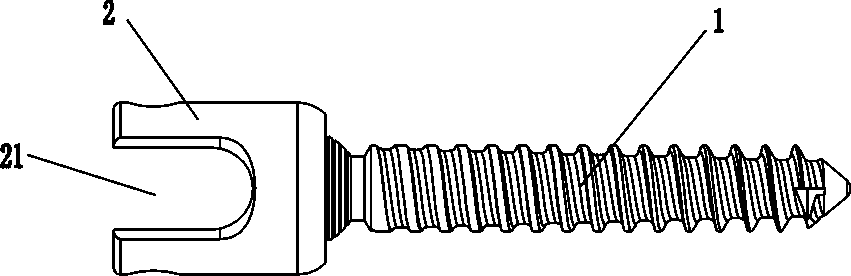
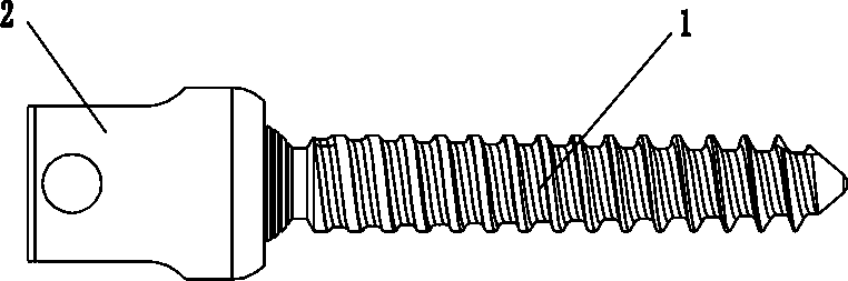
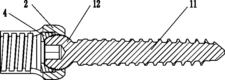
[0043] see figure 1 — Figure 12 , the present embodiment is made up of screw part and compression nut 3, and screw part includes screw head 1, screw cap 2 and clasp 4, and wherein screw head 1 and screw cap 2 are movable connection structures, and screw head 1 is provided with double The external thread of the wire thread. The tail of the nut 2 is provided with a U-shaped groove 21 with an internal thread, the compression nut 3 is installed in the U-shaped groove 21, and the external thread of the compression nut 3 is engaged with the internal thread of the U-shaped groove 21 , and the upper edge of the external thread of the compression nut 3 is provided with a boss 31 at the outermost edge. The boss 31 enables the outer thread of the compression nut 3 and the inner thread of the U-shaped groove 21 to be more firmly engaged with each other, so that slipping or loosening is not easy to occur.

[0044] The head of the screw cap 2 is provided with a flange 22 on the inner wa...

Embodiment 2

[0050] see Figure 15 — Figure 20 In this embodiment, an extension part 5 is provided at the tail of the screw cap 2, and a wedge-shaped groove 51 is provided between the extension part 5 and the tail of the screw cap 2. The effect of the extension part 5 is to help connect the connecting rod 7 in use, and after the connection rod 7 is installed, the extension part 5 is broken off and discarded.

[0051] The remaining structures and usage methods of this embodiment are the same as those of Embodiment 1.

Embodiment 3

[0053] see Figure 21 — Figure 26 , In this embodiment, a penetrating exudation hole 14 is provided in the screw head 1 for injecting fillers such as bone cement.

[0054] The remaining structures and usage methods of this embodiment are the same as those of Embodiment 1.


PUM


Abstract

The invention discloses a surgical instrument for medical treatment, in particular to a pedicle screw. The screw is composed of a screw part and a compression nut, the screw part comprises a screw head and a screw cap which are connected with each other, the screw head is provided with an external thread which is a double-line thread, and the tail of the screw cap is provided with a U-shaped groove provided with an internal thread; the pedicle screw is structurally characterized in that the compression nut is installed in the U-shaped groove, the external thread of the compression nut is meshed with the internal thread of the U-shaped groove, and a boss is arranged at the outermost edge of the upper edge of the external thread of the compression nut. The pedicle screw has the advantages of being simple in structure, high in strength, high in safety performance and not prone to sliding or loosening after being implanted into the human body.

Description

technical field [0001] The invention relates to a medical operation instrument, in particular to a pedicle screw. Background technique [0002] When the pedicle screw is used in conjunction with the connecting rod and the transverse connector, it needs to be fixedly connected with the connecting rod by compressing the fixing nut. After the connecting rod is placed in the U-shaped groove of the pedicle screw, the compression fixing nut is screwed into the U-shaped groove of the pedicle screw, and the compression fixing nut and the U-shaped groove are connected through thread engagement, but This type of connection is prone to slipping or loosening. [0003] According to whether the screw head can rotate in the screw cap, pedicle screws are mainly divided into two types: directional pedicle screws and universal pedicle screws. Wherein the screw head of the universal pedicle screw is composed of a rod body and a sphere, and the sphere in a spherical structure is placed in the...

Claims


Application Information

Patent Timeline
Patent Type & Authority Patents(China)
IPC IPC(8): A61B17/68A61B17/70A61B17/86
CPCA61B17/683A61B17/685A61B17/7001A61B17/7064A61B17/7074A61B17/8605A61B17/862A61B2017/564
Inventor 周建明
Owner ZHEJIANG KANGCI MEDICAL TECH
Why Eureka
Try Eureka