A kind of synchronous bottle unscrambling equipment

A bottle unscrambling and equipment technology, which is applied in the direction of conveyor objects, transportation and packaging, etc., to achieve the effects of increasing the bottle unscrambling speed, saving labor costs, and good bottle unscrambling effects

Active Publication Date: 2017-09-12
BEIJING DAHENG IMAGE VISION
View PDF19 Cites 0 Cited by
  • Summary
  • Abstract
  • Description
  • Claims
  • Application Information

AI Technical Summary

Problems solved by technology

[0006] Aiming at the above-mentioned problems encountered in the current bottle body, especially the production process of vials, the purpose of the present invention is to provide a synchronous bottle unscrambling equipment, through which the synchronous bottle unscrambling equipment can not only solve the problem of changing bottles with inconsistent directions of bottle openings Because of the problem of the same direction of the bottle mouth, and it is not necessary to add an extra section on the production line for unscrambling bottles, that is, it will not extend the production line, nor does it need to stop the bottle conveying device, which can increase the speed of unscrambling bottles, thereby Can greatly save labor costs

Method used


Image

  • A kind of synchronous bottle unscrambling equipment
  • A kind of synchronous bottle unscrambling equipment

Examples


Embodiment 1

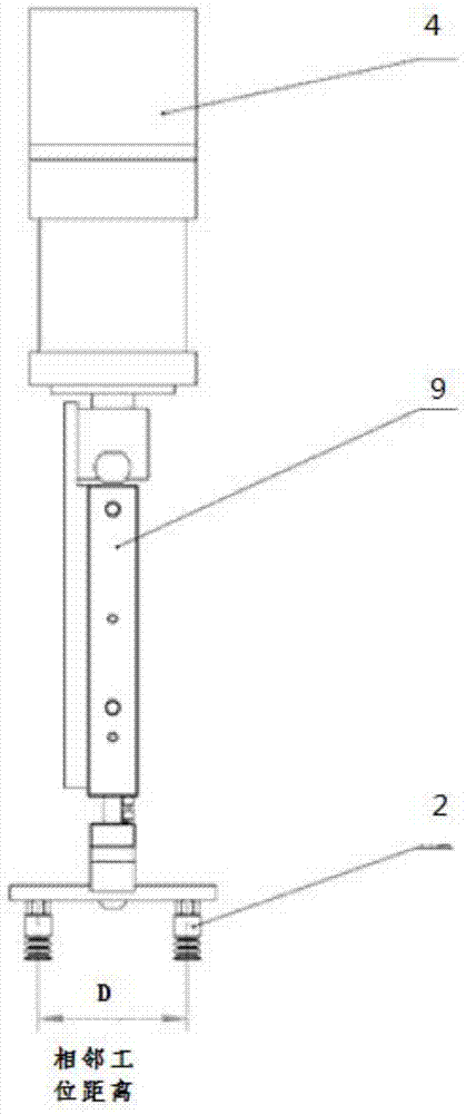
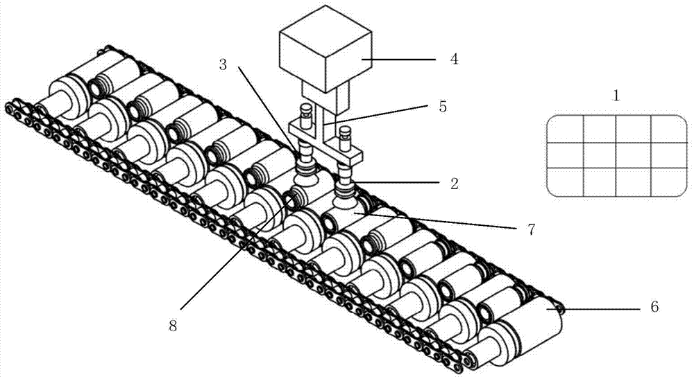
[0024] Embodiment 1 of the present invention provides a kind of synchronous bottle unscrambling equipment, its structure is as follows figure 1 As shown, it includes: a sensor 1 , a first suction cup 2 , a second suction cup 3 , a rotating device 4 and a bracket 5 . It also includes a control device, but it is not shown in the figure.

[0025] The sensor 1 is located upstream of the bottle conveying device 6. The conveying device 6 has a large number of conveying positions, and the interval between any two conveying positions is equal, and each conveying position will convey a bottle. The support 5 is installed below the rotating mechanism 4 , the first suction cup 2 and the second suction cup 3 are installed below the support 5 parallel to each other, and the mouth of the suction cups faces downward. The distance between two suction cups is equal to the distance between two adjacent transmission positions on the transmission device.

[0026] Such as figure 2 As shown, the...

Embodiment 2

[0033] In this embodiment, the synchronization device adopts a structure similar to that of Embodiment 1, including: a control device, a sensor, a first suction cup, a second suction cup and a rotating device.

[0034] Only in this embodiment, the first suction cup and the second suction cup are installed directly below the rotating mechanism, and the first suction cup and the second suction cup respectively have their own telescopic mechanisms, and the two telescopic mechanisms can work separately under the control of the controller. In this way, when a certain suction cup does not need to work, it will not fall, reducing the interference between the suction cup and the bottle body.

Embodiment 3

[0036] In this embodiment, the synchronization device also adopts a structure similar to that of Embodiment 1, including: a control device, a sensor, a first suction cup, a second suction cup and a rotating device.

[0037] However, in this embodiment, the first suction cup and the second suction cup are powerful suction cups, so they do not need to cooperate with the telescopic mechanism, and the bottle body can be sucked up at a certain distance from the bottle body.

[0038] It can be seen from the specific embodiment of the present invention that the present invention uses a sensor to detect the direction of the bottle, and then controls a group of moving devices to make the direction of the bottle consistent after the products with different directions of the bottle are jacked up and rotated, and then the bottle can be conveyed. In the process, the arrangement of the bottle body is completed, with ingenious structure, high efficiency and good applicability. Moreover, the ...


PUM


Abstract

The invention provides synchronous bottle arranging equipment which comprises a bottleneck direction detection device, a control device, a first sucking-up device, a second sucking-up device and a rotating mechanism. The synchronous bottle arranging equipment is mounted above a bottle body conveying device, and is used for sucking up reverse bottle bodies alternately through the first sucking-up device and the second sucking-up device, then realizing synchronous displacement of the sucked-up bottle bodies and the conveying device in the horizontal direction through rotation, meanwhile realizing the change of bottleneck direction detections through rotation, and replacing the bottle bodies on the conveying device. The synchronous bottle arranging equipment provided by the invention is simple and smart in structure, cannot affect the conveying speed of a production line, occupies no independent bottle arranging space, and can realize arrangement of bottleneck direction detections in the bottle body conveying process.

Description

technical field [0001] The invention relates to the field of bottle body production, in particular to a synchronous bottle unscrambling device. Background technique [0002] With the advancement of science and technology and the enrichment of material life, more and more packaging products have entered people's lives. As a packaging structure that is often used in people's daily life, bottles are being produced and used more and more widely. [0003] In particular, vials are widely used in the packaging of biopharmaceuticals, food and beverages, and daily chemical products, and their quality is directly related to the lives and health of the people. Therefore, in order to ensure the quality of the vials, it is necessary to carry out strict sorting and bottle sorting before the vials enter the warehouse. [0004] At present, in the field of vial production, most of them adopt the manual method for unscrambling bottles. This unscrambling method is not only slow, but also wa...

Claims


Application Information

Patent Timeline
Patent Type & Authority Patents(China)
IPC IPC(8): B65G47/22B65G47/91
CPCB65G47/22B65G47/914
Inventor 马玉朋孙岩杜戊王亚鹏陈绍义房超刘凤龙蔡文超
Owner BEIJING DAHENG IMAGE VISION
Why Eureka
Try Eureka