Releasable vacuum holding device

A support device, vacuum technology, applied in the field of detachable vacuum support devices

Active Publication Date: 2016-03-16
帕特里克・施密特
View PDF7 Cites 8 Cited by
  • Summary
  • Abstract
  • Description
  • Claims
  • Application Information

AI Technical Summary

Problems solved by technology

[0004] The problem at hand has been solved by the subje

Method used


Image

  • Releasable vacuum holding device
  • Releasable vacuum holding device
  • Releasable vacuum holding device

Examples


Embodiment Construction

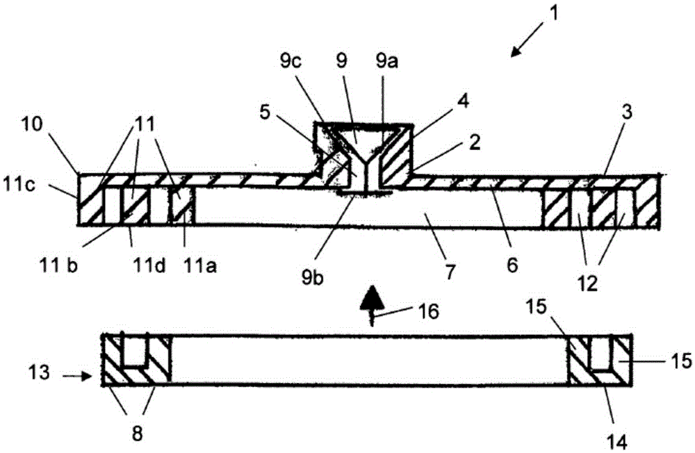
[0051] figure 1 A cross-sectional view of the support device (1) is shown with a support body (2), a dish-shaped base (3) and a dome-shaped support receptacle (4) protruding from the middle of the dish-shaped base. The vessel can be attached to the support receptacle (4); for this purpose, the latter is provided with an undercut (4a). The support receptacle (4) has an air duct (5).

[0052] When the substrate (3) is placed on a smooth wall (e.g. image 3 , 4 ), the vacuum chamber (7) is formed on the bottom (6) of the substrate (3). The valve (9) is located in the air duct (5) of the support housing (4) and is made of elastic material such as rubber with a cone (9a) and a cross bar (9b); the valve (9) is designed such that As air is sucked out of the vacuum chamber (7), the cone (9a) is lifted from its valve seat (9c) and closes onto the valve seat (9c) when the suction is complete. The task of the crossbar (9b) is to secure the valve (9) in the support receptacle (4). A...


PUM


Abstract

The invention relates to a releasable holding device (1) for attaching objects to a contact surface (8), with a vacuum chamber (7), which is open towards the contact surface (8) and in which, after application to the contact surface (8) by means of a suction device (20) generating a vacuum, a vacuum can be generated, the vacuum drawing the holding device (1) onto the contact surface (8) with the use of an elastic seal (13) which is provided towards the contact surface (8) and, in the event of a vacuum, brings about the adhesive connection to the contact surface (8), wherein the elastic seal (13) consists of at least one encircling seal which is U-shaped in profile and the limbs (15) of which engage over an encircling press-on web (11) of the holding body (2) and the foot surface (14) of which is firmly pressed in order to form the vacuum chamber (7) and the seal between web front edge (11b) and contact surface (8). Suction device and holding device are of two-part design.

Description

technical field [0001] The invention relates to a detachable vacuum support device for attracting objects to a contact surface, having a vacuum chamber opening towards the contact surface, and after contacting the contact surface with suction means for creating a vacuum, on the contact surface A vacuum is created in the vacuum chamber. Background technique [0002] WO01 / 20177A1 discloses a detachable supporting device that utilizes vacuum operation. The supporting device has a supporting body, which can be airtightly adsorbed to the air-tight contact surface by means of a seal made of elastic material and can be installed in devices for various load-bearing functions. The support body has a vacuum chamber opening towards the contact surface, the vacuum chamber has an elastic seal facing the contact surface, the support body has a valve facing the vacuum chamber, and when the support body is adsorbed on the contact surface, through the valve A vacuum can be created in the v...

Claims


Application Information

Patent Timeline
IPC IPC(8): F16B47/00A47G1/17
CPCA47G1/17F16B47/00F16M13/02
Inventor 哥特·波特斯帕特里克·施密特
Owner 帕特里克・施密特
Why Eureka
Try Eureka