Ejecting device for projector

A technology for a jacking device and a projector, which is applied to projection devices, instruments, optics, etc., can solve problems such as incongruity between left and right directions, affect teaching quality, and image distortion, and achieve the effect of being difficult to move.

Active Publication Date: 2016-03-16
无锡市东锦宏投资管理有限公司
View PDF5 Cites 0 Cited by
  • Summary
  • Abstract
  • Description
  • Claims
  • Application Information

AI Technical Summary

Problems solved by technology

[0003] In the past, in school multimedia classrooms, projectors were installed. The projectors are generally installed on the top of the wall. A controllable telescopic rod is installed above the projector. The telescopic rod is fixedly connected to the wall. Install the curtain on the wall, the installation position of the curtain needs to be determined according to the position of the projector, but often due to the deviation of the installation, the image projected by the projector on the curtain will be biased to one side of the curtain, and the up and down directions can be adjusted by telescopic rod adjustment, but the left and right directions of the projector cannot be adjusted, resulting in uncoordinated left and right directions of the resulting image, or distorting the image, thus affecting the quality of teaching

Method used


Image

  • Ejecting device for projector

Examples


Embodiment Construction

[0012] The present invention will be described in further detail below by means of specific embodiments:

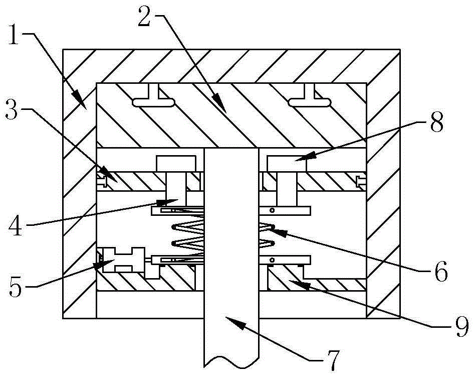
[0013] The reference numerals in the accompanying drawings of the description include: chute 1, slide block 2, support plate 3, top block 4, second cylinder 5, scissor lift 6, telescopic rod 7, rubber block 8, bottom plate 9.

[0014] Example basic reference figure 1 Shown: the jacking device for the projector, installed on the wall, including the telescopic rod 7, above the telescopic rod 7, there is a chute 1 fixed in the wall, and the chute 1 is slidably connected with the slider 2, the chute 1 One end of the movement track of the inner slider 2 is provided with a first cylinder, the slider 2 is connected to the first cylinder, the telescopic rod 7 is welded on the slider 2, and the support plate 3 is slidably connected between the two side walls of the chute 1 And be positioned at the base plate 9 below the support plate 3, telescoping rod 7 passes support plate 3 an...


PUM


Abstract

The invention relates to an adjusting device, and discloses an ejecting device for a projector. The ejecting device is arranged on a wall and comprises a telescopic rod. A sliding groove is formed in the wall. A sliding block is connected with the sliding groove in a sliding manner. The telescopic rod is fixedly connected to the sliding block. A supporting plate and a bottom plate located below the supporting plate are connected between the two side walls of the sliding groove in a sliding manner. The telescopic rod penetrates the supporting plate and the bottom plate and is in clearance fit with the supporting plate and the bottom plate. Ejector blocks penetrating the supporting plate are arranged on the supporting plate. A shear fork type lifter is arranged below the ejector blocks in an abutting manner and fixedly connected to the bottom plate. Compared with the prior art, images formed by the projector can be more coordinated through left and right movement of the sliding block.

Description

technical field [0001] The invention relates to a clamping device for a projector. Background technique [0002] A projector, also known as a projector, is a device that can project images or videos onto a screen. It can be connected to a computer, VCD, DVD, BD, game console, DV, etc. through different interfaces to play the corresponding video signal. Projectors are widely used in homes, offices, schools, and entertainment venues. According to different working methods, there are different types such as CRT, LCD, and DLP. [0003] In the past, in school multimedia classrooms, projectors were installed. The projectors are generally installed on the top of the wall. A controllable telescopic rod is installed above the projector. The telescopic rod is fixedly connected to the wall. Install the curtain on the wall, the installation position of the curtain needs to be determined according to the position of the projector, but often due to the deviation of the installation, the ...

Claims


Application Information

Patent Timeline
Patent Type & Authority Applications(China)
IPC IPC(8): F16M13/02F16M11/04F16M11/18G03B21/54
CPCF16M11/046F16M11/18F16M13/02G03B21/54
Inventor 任博
Owner 无锡市东锦宏投资管理有限公司
Why Eureka
Try Eureka