
Air output assembly and air conditioner with same

A technology for air outlet components and air conditioners, which can be used in home appliances, air flow control components, space heating and ventilation details, etc., and can solve problems such as small sweeping range.

Active Publication Date: 2016-03-09
GREE ELECTRIC APPLIANCES INC
View PDF6 Cites 6 Cited by
  • Summary
  • Abstract
  • Description
  • Claims
  • Application Information

AI Technical Summary

Problems solved by technology

[0004] The main purpose of the present invention is to provide an air outlet assembly and an air conditioner with it, so as to solve the problem of small sweeping range in the prior art

Method used


Image

  • Air output assembly and air conditioner with same
  • Air output assembly and air conditioner with same
  • Air output assembly and air conditioner with same

Examples


Embodiment Construction

[0037] It should be noted that, in the case of no conflict, the embodiments in the present application and the features in the embodiments can be combined with each other. The present invention will be described in detail below with reference to the accompanying drawings and examples.

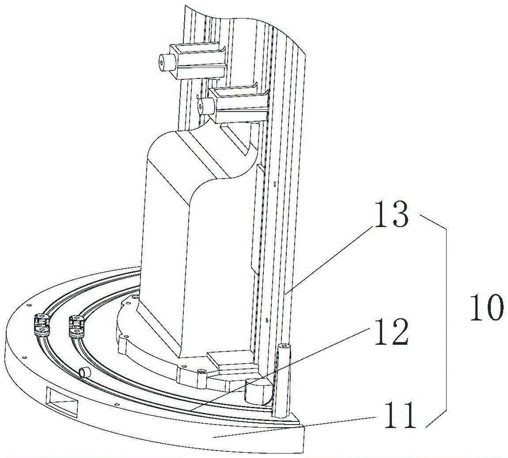
[0038] Such as image 3 and Figure 4 As shown, according to an embodiment of the present invention, an air outlet assembly is provided, and the air outlet assembly includes a support part 10, a guide rail part 20, a rotary driving part and an air outlet part. The supporting part 10 has a first arc guide groove 12 . The guide rail part 20 is connected with the support part 10 and has a second arc-shaped guide groove 21 corresponding to the first arc-shaped guide groove 12 . The rotary driving part 30 includes a driving assembly 31, the driving assembly 31 has at least two oppositely arranged driving rollers 310, one driving roller 310 is located in the first arc-shaped guide groove 12, and t...


PUM


Abstract

The invention provides an air output assembly and an air conditioner with the same. The air output assembly comprises a supporting part, a guide rail part, a rotating driving part and an air output part, wherein the supporting part is provided with a first arc-shaped guiding groove, and the guide rail part is connected with the supporting part and provided with a second arc-shaped guiding groove corresponding to the first arc-shaped guiding groove; the rotating driving part comprises a driving assembly which is provided with at least two oppositely-arranged driving rollers, one driving roller is located in the first arc-shaped guiding groove, and the other driving roller is located in the second arc-shaped guiding groove; the air output part is provided with an air outlet, is connected with the rotating driving part and synchronously rotates with the rotating driving part. By means of the air output assembly and the air conditioner with the same, the problem that the air sweeping range is small in the prior art is effectively solved.

Description

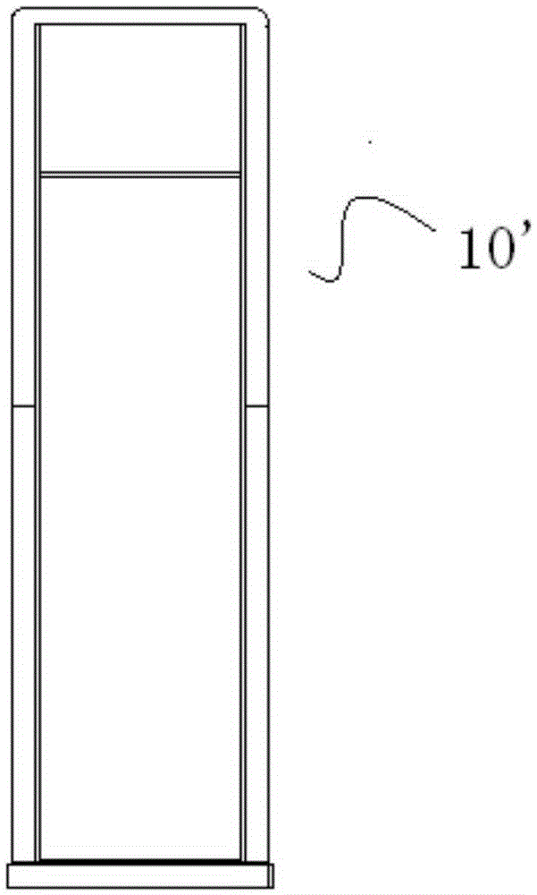
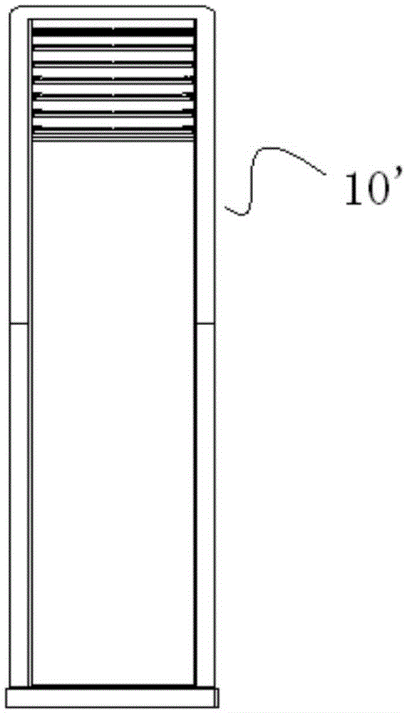
technical field [0001] The invention relates to the technical field of air conditioning, in particular to an air outlet component and an air conditioner with the same. Background technique [0002] Such as figure 1 and figure 2 As shown, the air outlet is generally fixed on the air conditioner 10' at present, and the schematic diagram of the whole machine is used to cover the air outlet by moving the sliding door up and down, as shown in figure 1 Shown is the state where the sliding door covers the air outlet, figure 2 This is the state where the sliding door panel is lowered to expose the air outlet. The sliding door panel that shields the air outlet is generally realized by the meshing between the rack and pinion. When the air conditioner works to supply air after the sliding door is lowered, the sweeping blades swinging left and right can be used to slightly change the airflow angle of the air outlet of the air conditioner, and the air supply angle is small. [000...

Claims


Application Information

Patent Timeline
Patent Type & Authority Applications(China)
IPC IPC(8): F24F13/14
CPCF24F13/14F24F13/1426F24F2013/1446
Inventor 陈诚朱日荣陈珠秀张辉梁博叶务占肖林辉林金煌何振健
Owner GREE ELECTRIC APPLIANCES INC
Learn More