injection molding machine

A technology of injection molding machine and mold clamping mechanism, applied in the field of injection molding machines, can solve the problems of undocumented configuration, difficulty in operation of a circuit breaker 6 for power cut off, and difficulty in operation.

Active Publication Date: 2017-11-10
FANUC LTD
View PDF1 Cites 0 Cited by
  • Summary
  • Abstract
  • Description
  • Claims
  • Application Information

AI Technical Summary

Problems solved by technology

Therefore, the operation of the circuit breaker 6 for power cutoff may become difficult
In particular, when the injection mechanism 2 mounted on the machine base 4 protrudes greatly from the base 4, it is necessary to drill under the injection mechanism 2 to operate the power cutoff circuit breaker 6, so the operation may become more difficult.
[0010] In the aforementioned Japanese Patent Application Laid-Open No. 11-268094, it is described that a power cut-off machine is arranged on the operation side of the front surface, but the specific arrangement method, etc. are not described.

Method used


Image

  • injection molding machine
  • injection molding machine
  • injection molding machine

Examples


Embodiment Construction

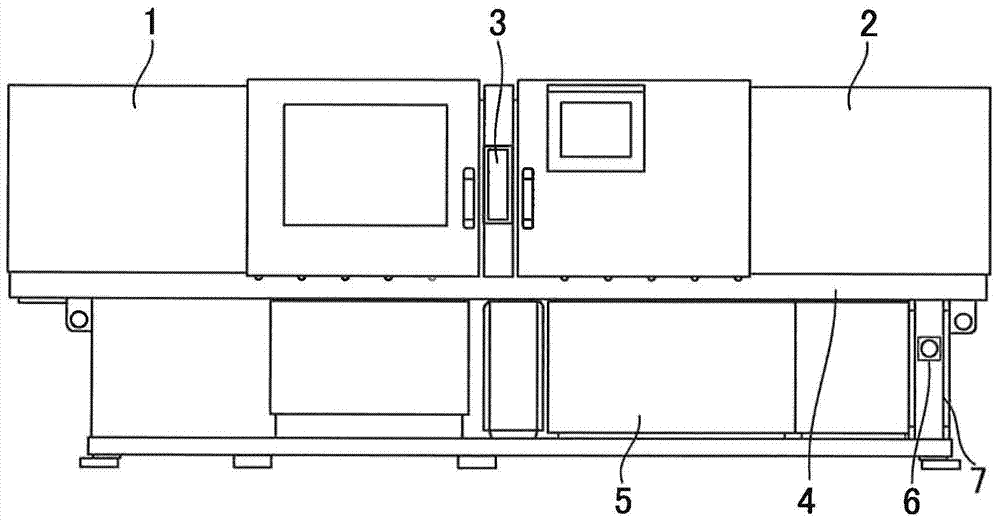
[0025] First, use Figure 1 to Figure 3 A first embodiment of the injection molding machine of the present invention will be described.

[0026] Such as figure 1 As shown, the injection molding machine includes: a mold clamping mechanism 1 that opens and closes a metal mold and generates mold clamping force; an injection mechanism 2 that is arranged opposite to the mold clamping mechanism 1 and melts resin and injects it into the metal mold; The operation panel 3 used to operate the injection molding machine; the machine table 4; and the electrical equipment part 5 that drives the mold clamping mechanism 1 and the injection mechanism 2. The operation panel 3 is disposed facing the front of the injection molding machine. The mold clamping mechanism 1 and the injection mechanism 2 are mounted on a machine base 4 . The electrical equipment unit 5 is arranged inside the machine base 4 .

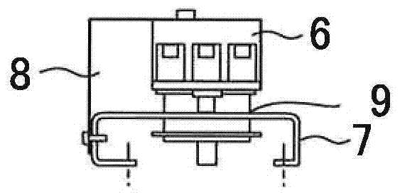
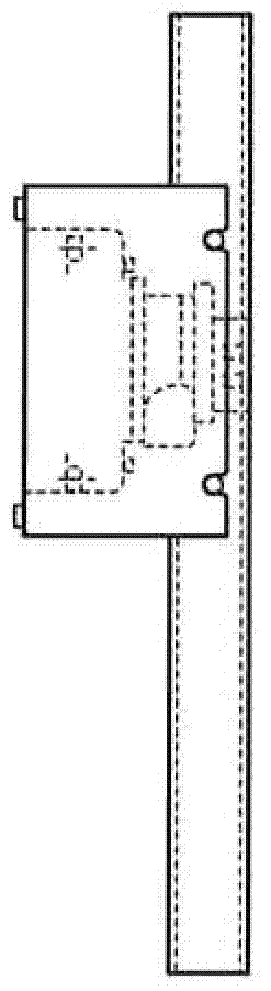
[0027] The pillar 7 constituting the machine table 4 is composed of a columnar member wi...


PUM


Abstract

The invention provides an injection molding machine which comprises a structure comprising a clamping mechanism and an injection mechanism on a machine, and the machine comprises a circuit breaker which can cut the electric power supply of electric equipment, and the electric equipment is used for driving the clamping mechanism and the injection mechanism. Total or a part of the circuit breaker is arranged in a prop which can form the machine. The unavailable space on the rear of the circuit breaker can be reduced according to the above arrangement.

Description

technical field [0001] The present invention relates to an injection molding machine equipped with a circuit breaker for power cutoff on a machine base of the injection molding machine. Background technique [0002] use Figure 6 as well as Figure 7A to Figure 7C An example of a conventional injection molding machine will be described. [0003] Such as Figure 6 As shown, the injection molding machine includes: a mold clamping mechanism 1 that opens and closes a metal mold and generates mold clamping force; an injection mechanism 2 that is arranged opposite to the mold clamping mechanism 1 and melts resin and injects it into the metal mold; The operation panel 3 used to operate the injection molding machine; the machine table 4; and the electrical equipment part 5 that drives the mold clamping mechanism 1 and the injection mechanism 2. The operation panel 3 is disposed facing the front of the injection molding machine. The mold clamping mechanism 1 and the injection mech...

Claims


Application Information

Patent Timeline
Patent Type & Authority Patents(China)
IPC IPC(8): B29C45/76
CPCB29C45/7666B29C2945/76521
Inventor 菅原圭介西村浩一
Owner FANUC LTD
Why Eureka
Try Eureka