Detachable ornament structure
A detachable and jewelry technology, which is applied in the direction of clothing, decorative chains, bracelets, etc., can solve the problems of inconvenient disassembly, inconvenient replacement, inconvenient free matching, etc., and achieve the effect of improving utilization rate, convenient disassembly, and simple structure
- Summary
- Abstract
- Description
- Claims
- Application Information
AI Technical Summary
Problems solved by technology
Method used
Image

Examples
Embodiment 1
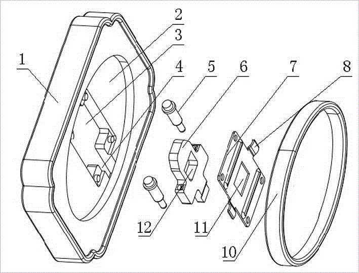
[0028] Such as figure 1 and figure 2 As shown, a detachable jewelry structure includes a decoration main body 1 and a tray 10, and the decoration main body 1 and the tray 10 form a detachable connection form through a connecting part;
[0029] The connecting part includes a first elastic part 5 and an engaging plate 6. The main body of the decorative part 1 is provided with a mounting groove 3, and one end of the mounting groove 3 is provided with a through-section 4 penetrating with any side of the main body of the decorative part 1. The engaging plate 6 and the first elastic part 5 are arranged in the installation groove 3, and the two ends of the first elastic part 5 respectively act on the wall surface of the installation groove 3 and the engaging plate 6, and the deformation direction of the first elastic part 5 is located at the two ends. On the connecting line of the end, the through section 4 and the first elastic part 5 are respectively located on the opposite sides...
Embodiment 2
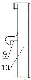
[0036] Such as figure 1 and figure 2 As shown, this embodiment is further limited on the basis of Embodiment 1: in order to facilitate the aesthetics of the connection between the decoration and the main body 1 of the decoration when the tray 10 is used as a decoration carrier, as a kind of tray 10, all or part of the The structural form of embedding the main body 1 of the decoration and covering the parts such as the clamping plate 6, the main body of the decoration 1 is also provided with a tray hole 2 whose shape fits the shape of the bottom of the tray 10, and the installation groove 3 is located in the tray hole 2 on the underside. In this structure, the tray hole 2 is a position limiting portion for defining the projected position of the tray 10 on the trim body 1 .
[0037] In order to realize that no compressive stress is applied to the engaging plate 6 by the through section 4, the hook segment can also extend into the accommodating gap when the tray 10 is inserted...
Embodiment 3
[0039] Such as figure 1 and figure 2 As shown, this embodiment is further limited on the basis of Embodiment 1. As a structural form with good performance in guiding the movement of the engaging plate 6 in the installation groove 3, the first elastic part 5 includes a guide rod and a sleeve The spring on the guide rod, the engaging plate 6 is also provided with a blind hole for accommodating the first elastic part 5 . In the above structure, as a specific implementation method, it is preferable to set the guide rod in the shape of a stepped shaft, and one end of the spring is sleeved on the small end of the stepped shaft. At this time, the end of the spring is in contact with the shaft shoulder, and the other end of the spring embedded in blind holes.
[0040] In order to further optimize the guiding performance of the first elastic part 5 to the movement of the engaging plate 6 in the installation groove 3, there are two first elastic parts 5, and the two first elastic par...
PUM
 Abstract
Description
Claims
Application Information
 - R&D
- Intellectual Property
- Life Sciences
- Materials
- Tech Scout
- Unparalleled Data Quality
- Higher Quality Content
- 60% Fewer Hallucinations
Browse by: Latest US Patents, China's latest patents, Technical Efficacy Thesaurus, Application Domain, Technology Topic, Popular Technical Reports.
© 2025 PatSnap. All rights reserved.Legal|Privacy policy|Modern Slavery Act Transparency Statement|Sitemap|About US| Contact US: help@patsnap.com