


Quick Research
Generate reliable direction feasibility study reports for your R&D in just a few steps.

Technical Q&A
Discover and master advanced knowledge NOW. Basics, ideas, possibilities, all at once.

Find Solutions
As an expert in R&D theories, this can generate solutions to your technical problems instantly.

Evaluate Feasibility
Analyze your overall solution with one click, know your potential R&D risks in advance.

Monitor Landscape
Get weekly tech updates, stay abreast of the latest tech innovations and key insights.
A kind of thin-layer optical glue elastic modulus test method and sample
A technology of elastic modulus and test method, which is applied in the direction of applying stable tension/pressure to test the strength of materials, etc., can solve the problem that it cannot be used to measure the elastic modulus of thin-layer optical adhesives, and achieves the promotion of technology research and development and optimization, The effect of great practical application value and simple derivation method
- Summary
- Abstract
- Description
- Claims
- Application Information
AI Technical Summary
Problems solved by technology
Method used
Image

Examples
Embodiment 1
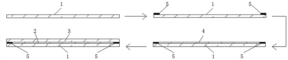
[0079] (1) Clean the bottom glass and the upper glass, the thickness of the bottom glass and the upper glass is 0.7mm, and the diagonal length is 20mm×50mm;
[0080] (2) Mix the glue of the A and B components of the optical glue in a ratio of 1:1, fully stir and defoam, to form a usable liquid optical glue;
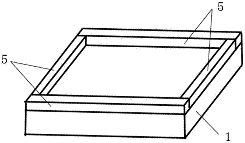
[0081] (3) Adhesive tapes with a thickness of 200 μm are fixed at the four corners of the bottom glass 1;
[0082] (4) Pour the liquid optical glue on the bottom glass and let it stand until the liquid optical glue flows freely and completely covers the bottom glass;
[0083] (5) Place the upper glass on the bottom glass and the liquid optical glue to form a sample with a three-layer structure;
[0084] (6) Put the sample into the oven for 3 hours, set the oven temperature to 70°C, and the liquid optical glue between the two layers of glass becomes solid optical glue;
[0085] (7) Bond the strain gauge at the center of the cured sample;
[0086] (8) Fix the cured sampl...
Embodiment 2
[0092] In order to solve the difficult problem of testing the modulus of elasticity of optical glue with a fixed thickness of only a few hundred microns, the present invention proposes a method for testing the modulus of elasticity of thin-layer optical glue, which includes the following steps:
[0093] (1) Clean the bottom glass and the upper glass, the thickness of the bottom glass and the upper glass is 1.1mm, and the size is 174mm×315mm;
[0094] (2) Mix the glue of the A and B components of the optical glue according to the ratio of 1:1, fully stir and defoam, and form a usable optical glue;
[0095] (3) Fix tape with a thickness of 250 μm on the four corners of the bottom glass;
[0096] (4) Pour the optical glue on the bottom glass and let it stand until the optical glue flows freely and completely covers the bottom glass;
[0097] (5) Put the sample into the oven for 3 hours, set the oven temperature to 70°C, and the liquid optical glue between the two layers of glass...
PUM
| Property | Measurement | Unit |
|---|---|---|
| thickness | aaaaa | aaaaa |
| tensile load | aaaaa | aaaaa |
| thickness | aaaaa | aaaaa |
Abstract
Description
Claims
Application Information
 - R&D Engineer
- R&D Manager
- IP Professional
- Industry Leading Data Capabilities
- Powerful AI technology
- Patent DNA Extraction
Browse by: Latest US Patents, China's latest patents, Technical Efficacy Thesaurus, Application Domain, Technology Topic, Popular Technical Reports.
© 2024 PatSnap. All rights reserved.Legal|Privacy policy|Modern Slavery Act Transparency Statement|Sitemap|About US| Contact US: help@patsnap.com