
Stair surface scribing tool

A scribing tool and step surface technology, applied in the field of step surface scribing tools, can solve the problems of inaccurate scribing, inconvenient operation, and difficulty in meeting actual needs, and achieve the effect of accurate scribing and easy operation.

Active Publication Date: 2016-02-24
AVIC CHENGFEI COMML AIRCRAFT COMPANY
View PDF8 Cites 1 Cited by
  • Summary
  • Abstract
  • Description
  • Claims
  • Application Information

AI Technical Summary

Problems solved by technology

In the process of using the existing scribing tools to draw lines on two surfaces that are not in the same plane, and use one of the higher surfaces as a reference to draw lines on the other lower surface, there are inconveniences in operation and Inaccurate lines and other problems, it is difficult to meet the actual needs

Method used


Image

  • Stair surface scribing tool
  • Stair surface scribing tool

Examples


Embodiment approach

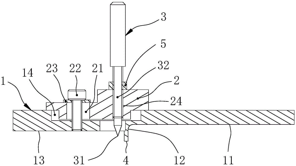
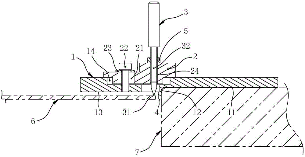
[0018] Such as figure 1 As shown, the stepped surface scribing tool includes a bottom plate 1 with a positioning structure, a slider 2 arranged on the bottom plate 1, and a scribe needle 3; the scribe needle 3 is arranged on the slider 2, and its scribe end 31 from The lower side of the base plate 1 is protruded, and the scribe needle 3 can move vertically to adjust the protruding amount of the scribe end 31 . Wherein, the positioning structure of the base plate 1 is usually arranged on the lower side of the base plate 1, and it can have various embodiments, for example: positioning pins or positioning nails arranged on the lower side of the base plate 1, and positioned on the lower side of the base plate 1 and downward. The raised boss, the positioning formed by the structure of the lower side of the bottom plate 1 or other positioning structures matching the reference, and the like. When the marking needle 3 is set, it is enough to ensure that it can move in the vertical di...


PUM


Abstract

The invention discloses a stair surface scribing tool convenient for scribing lines on step surfaces. The stair surface scribing tool comprises a bottom plate with a positioning structure, a slider arranged on the bottom plate and a scriber, wherein the scriber is arranged on the slider, the scribing end extends out from the lower side surface of the bottom plate, and the scriber can move in the vertical direction so as to regulate the extension quantity of the scribing end. Through regulating the extension quantity of the scribing section of the scriber from the lower side surface of the bottom plate, the step difference between two surfaces on the same plane is adapted, the function of scribing lines on the step surfaces is realized, and the operation is simple and convenient. At the same time, lines are scribed after positioning is carried out through the positioning structure of the bottom plate, so that lines are more accurately scribed.

Description

technical field [0001] The invention relates to a scribing tool, in particular to a step surface scribing tool. Background technique [0002] At present, existing marking tools can only carry out marking work in the same plane. However, in engineering practice, it is often necessary to draw lines on the step surface of the same part, or to draw lines on the surfaces of two or more parts with both a certain step difference and a certain gap. In the process of using the existing scribing tools to draw lines on two surfaces that are not in the same plane, and use one of the higher surfaces as a reference to mark the other lower surface, there are inconveniences in operation and Inaccurate lines and other problems, it is difficult to meet the actual needs. Contents of the invention [0003] The technical problem to be solved by the present invention is to provide a step surface scribing tool which is convenient for scribing lines on the step surface. [0004] The technical ...

Claims


Application Information

Patent Timeline
Patent Type & Authority Applications(China)
IPC IPC(8): B25H7/04
CPCB25H7/04
Inventor 罗茂边毅
Owner AVIC CHENGFEI COMML AIRCRAFT COMPANY
Learn More