
An active card power source management device and method

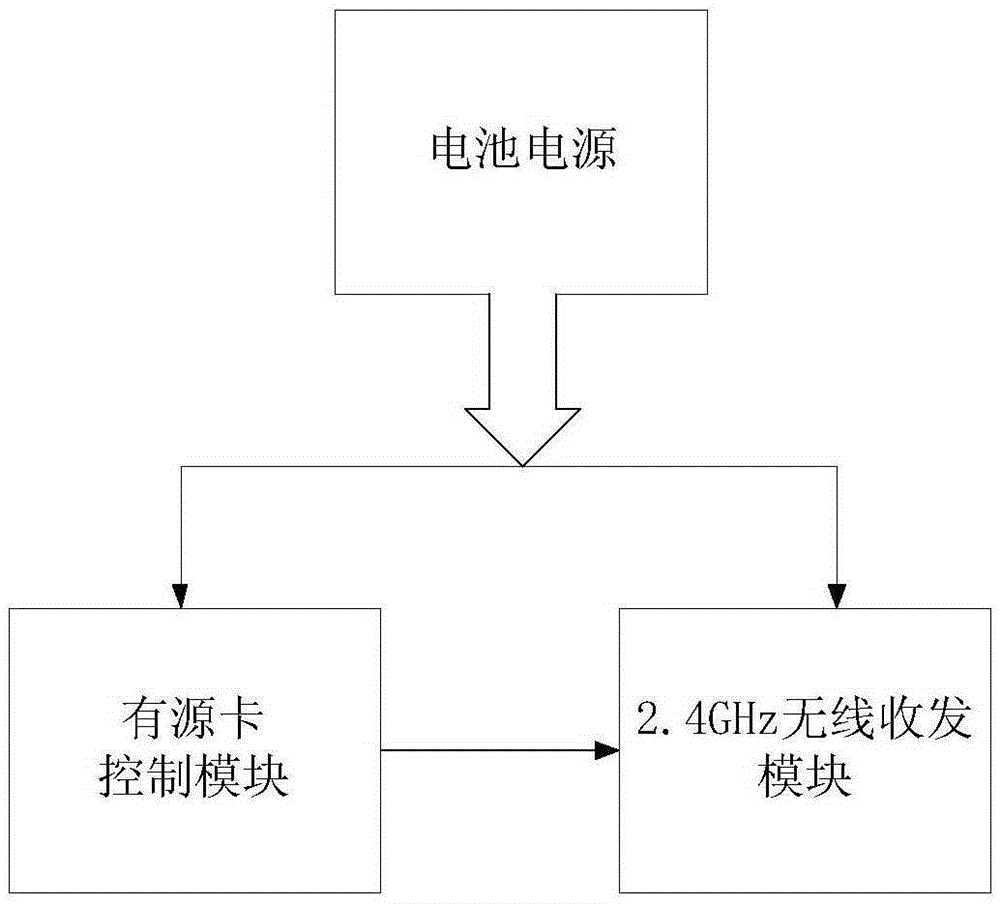
A power management device and power management technology, applied in the field of radio frequency identification, can solve the problems of high power consumption and affecting the effective service life of active cards, and achieve the effect of meeting mass production and stocking, improving effective use time, and ensuring service life

Active Publication Date: 2016-02-10
WUHAN RUINAJIE ELECTRONICS TECH
View PDF5 Cites 4 Cited by
  • Summary
  • Abstract
  • Description
  • Claims
  • Application Information

AI Technical Summary

Problems solved by technology

[0004] The embodiment of the present invention provides an active card power management device and method, aiming at solving the problem of high power consumption in the production and stocking stage of the active card in the prior art, which affects the effective service life of the active card

Method used


Image

  • An active card power source management device and method
  • An active card power source management device and method
  • An active card power source management device and method

Examples


Embodiment 1

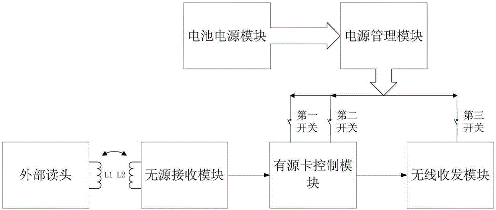
[0039] figure 2 A specific structural block diagram of the active card power management device provided by Embodiment 1 of the present invention is shown. For convenience of description, only parts related to the embodiment of the present invention are shown. In this embodiment, the active card power management device includes: a battery power module, a power management module electrically connected to the battery power module, and electrically connected to the power management module through a first switch and a second switch The active card control module, the wireless transceiver module electrically connected with the power management module through the third switch, and the passive receiving module electrically connected with the active card control module, the active card control module It includes a constant current zone and a non-constant current zone, the constant current zone is electrically connected to the power management module through a first switch, and the non...

Embodiment 2

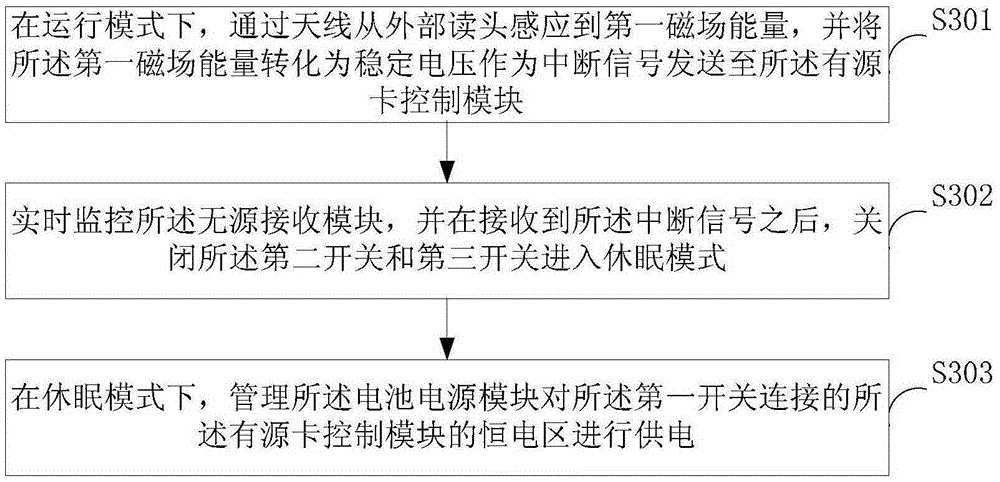
[0051] image 3 The implementation flow of the active card power management method provided by Embodiment 2 of the present invention is shown, and the details are as follows:

[0052] It should be noted that the active card includes a battery power module, a power management module electrically connected to the battery power module, and an active card electrically connected to the power management module through a first switch and a second switch. A control module, a wireless transceiver module electrically connected to the power management module through a third switch, and a passive receiving module electrically connected to the active card control module, the active card control module includes a constant current area and a non-constant current zone, the constant current zone is electrically connected to the power management module through a first switch, and the non-constant current zone is electrically connected to the power management module through a second switch.

[...


PUM


Abstract

The invention relates to the technical field of radio frequency identification and provides an active card power source management device and method. The device comprises a battery power source module, a power source management module, an active card control module, a wireless transmitting and receiving module and a passive receiving module. The method comprises the steps of in an operating mode, sensing first magnetic field energy from an external reading head via an antenna, converting the first magnetic field energy into steady voltage and sending the steady voltage to the active card control module as an interrupt signal; monitoring the passive receiving module in real time; turning off a second switch and a third switch to enter a sleep mode after receiving the interrupt signal; in the sleep mode, managing the battery power source module to supply power to a constant electricity area of the active card control module connected with a first switch. The requirements for the service life and the volume production and stock of active cards are met, the effective use life of power sources is prolonged and the service life thereof is guaranteed.

Description

technical field [0001] The invention belongs to the technical field of radio frequency identification, in particular to an active card power management device and method. Background technique [0002] At present, radio frequency identification technology is divided into three categories: passive identification, active identification and semi-active according to the energy supply method. The reading and writing distance of passive identification is short, and the price is low; the reading and writing distance of active identification can provide longer, but need battery power supply, the cost is higher; semi-active identification is between the two. The existing 2.4GHz frequency band communication radio frequency card adopts an active method to realize the transmission of medium and long-distance signals. The circuit in the active card is completely powered by the internal battery power supply, so the power consumption of the internal circuit is directly related to the use of...

Claims


Application Information

Patent Timeline
Patent Type & Authority Applications(China)
IPC IPC(8): G06K7/00
Inventor 彭颖吴水源张明宇陈毅成
Owner WUHAN RUINAJIE ELECTRONICS TECH
Learn More