
Indoor detachable substance drying lifting frame with good fixation performance

A fixed, lifting rack technology, applied in the field of indoor detachable drying racks and household products, can solve the problems of accumulation or blowing of drying objects, inconvenience in taking and placing drying objects, etc., and achieves convenient transportation, stability and protection. Good sex, fast lifting effect

Inactive Publication Date: 2016-01-27
万世蓉
View PDF3 Cites 0 Cited by
  • Summary
  • Abstract
  • Description
  • Claims
  • Application Information

AI Technical Summary

Problems solved by technology

[0004] The problem to be solved by the present invention is to provide a detachable lifting frame for drying indoors with good fixity, thereby solving the problem that the drying objects are easily piled up or blown off due to the influence of wind force, and the problem of inconvenient taking and placing of the drying objects

Method used


Image

  • Indoor detachable substance drying lifting frame with good fixation performance
  • Indoor detachable substance drying lifting frame with good fixation performance
  • Indoor detachable substance drying lifting frame with good fixation performance

Examples


Embodiment 1

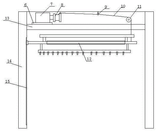
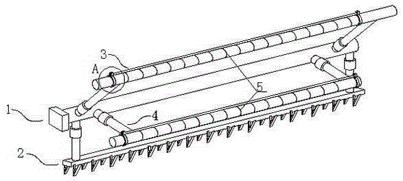
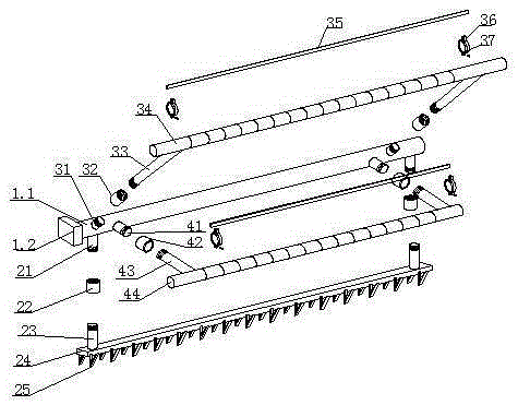
[0024] Such as Figure 1-Figure 5 The detachable lifting rack for indoor drying of described fixed objects includes a lifting device and a drying assembly 12, and the lifting device includes a micromotor 7 and a roller 11 arranged on the upper end of the indoor ceiling board 13, and the output of the micromotor 7 The shaft is connected with a lifting wire reel 8, and the lifting wire 10 of the lifting wire reel 8 passes through the conductive coil 9 and the roller 11 and then connects to the drying assembly 12; the drying assembly 12 is located at the lower end of the indoor ceiling board 13, and the drying assembly 12 includes a fixed Frame 1, the fixed frame 1 is detachably connected with the lower clamping assembly 2, the horizontal object assembly 4 and the upper object assembly 3, the fixed frame 1 includes a connecting rod 1.1; the lower clamping assembly 2 includes a connecting rod The threaded lower connector 21 at the lower end of the rod 1.1, the threaded lower conne...

Embodiment 2

[0031] This embodiment adds the following structure on the basis of Embodiment 1: one end of the connecting rod 1.1 is provided with a square positioning block 1.2, and the indoor side wall 14 at the lower end of the indoor ceiling board 13 is provided with a square positioning block 1.2. Vertical guide groove 15.

[0032] In this embodiment, in order to avoid the problem of inclination of the drying assembly 12 due to the unequal weight of the drying objects on the upper drying rod 34 and the horizontal drying rod 44, and to make the lifting more smooth, a square positioning block is set at one end of the connecting rod 1.1 1.2, the indoor side wall 14 at the lower end of the indoor ceiling board 13 is provided with a vertical guide groove 15 that cooperates with the square positioning block 1.2, no matter where the object drying assembly 12 is at any position, the square positioning block 1.2 is matched with the vertical guide groove 15, which can Ensure that the position of...

Embodiment 3

[0034] This embodiment is optimized as follows on the basis of embodiment 1 or embodiment 2: the upper end of the lower parallel drying rod 44 is also provided with the pressing device.

[0035] In order to ensure that the drying objects can be fixed firmly in this embodiment, the above-mentioned pressing device is also arranged on the upper end of the lower parallel drying object bar 44, and the drying objects at the upper end of the lower parallel drying object bar 44 can be fixed by the pressing device.


PUM


Abstract

The present invention discloses an indoor detachable substance drying lifting frame with good fixation performance. The indoor detachable substance drying lifting frame comprises a lifting device and a drying component. The lifting device comprises a micro motor arranged at the upper end of an indoor ceiling plate and a roller. The output shaft of the micro motor is connected to a lifting wire coil. The lifting wire of the lifting wire coil goes through a wire guide ring and the roller to be connected to the drying component. The drying component comprises a fixed frame which is detachably connected to a lower clamp component, a horizontal drying component and an upper drying component. The drying component is provided with a pressing device. The pressing device comprsises fixed clamp hoops. The upper ends of the fixed clamp hoops are provided with fixed buckles, and pressing plates are clamped between the fixed buckles. According to the indoor detachable substance drying lifting frame, through arranging the detachable pressing device, the device can be installed according to user needs, the lifting is convenient, and the fixation and protection performance are good.

Description

technical field [0001] The invention relates to a household item, which belongs to the field of daily necessities, in particular to a detachable lifting frame for indoor drying with good fixity. Background technique [0002] With the rapid increase of the urban population and the increasing number of urban residents, the corresponding urban residential buildings have also increased significantly. Nowadays, in order to meet the needs of a large number of working-class residents, many small-sized houses have appeared. In order to expand the indoor area, many houses are mostly designed to connect the living balcony with the living room, or there is no living balcony directly, which is for the living room to dry clothes. , quilts, etc. have brought inconvenience, and the protective railings of the current residential windows cannot protrude from the outer wall. Therefore, residents can only design the clothes drying rack indoors near the window, and the clothes, etc. are dried i...

Claims


Application Information

Patent Timeline
Patent Type & Authority Applications(China)
IPC IPC(8): D06F57/12
CPCD06F57/12
Inventor 万世蓉
Owner 万世蓉
Learn More