Tension control device for padder

A technology of tension control and padding, which is applied in the textile field, can solve the problems of affecting the stretching effect and uneven stretching of fabrics, and achieve the effect of improving the stretching effect and improving the quality of tie-dyeing

Inactive Publication Date: 2016-01-27
TIANJIN DEK CHEM
View PDF0 Cites 1 Cited by
  • Summary
  • Abstract
  • Description
  • Claims
  • Application Information

AI Technical Summary

Problems solved by technology

[0003] The tension control system currently used in said process does not stretch the fabric uniformly, which affects the stretching effect

Method used


Image

  • Tension control device for padder
  • Tension control device for padder

Examples


Embodiment Construction

[0015] The present invention will be described in detail below with reference to the accompanying drawings and examples.

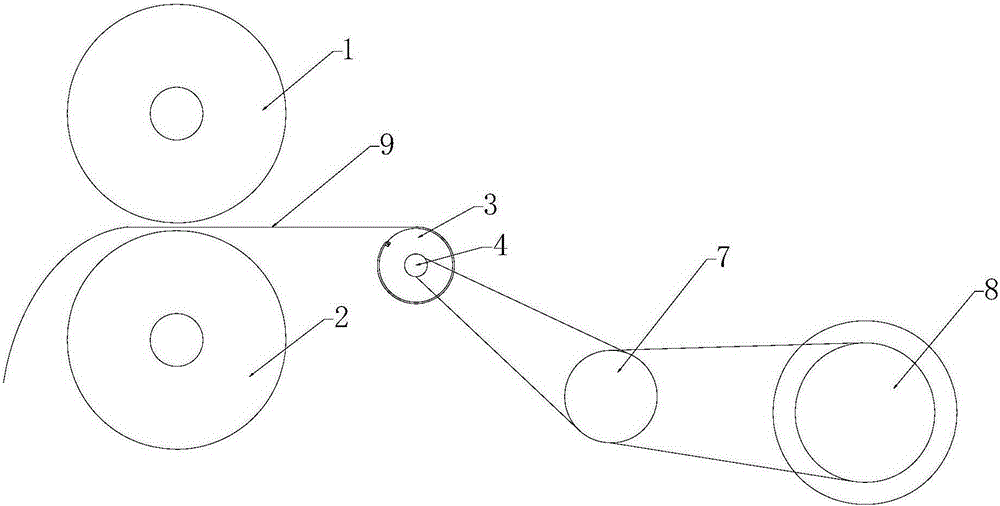
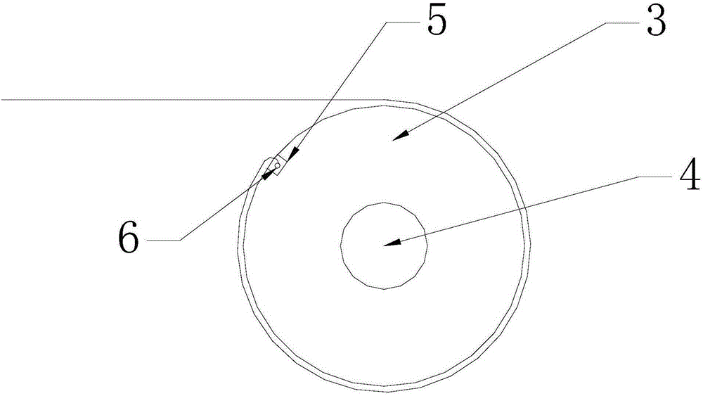
[0016] Such as Figure 1-2 As shown, a rolling car tension control device includes a driven roller 1, a driving roller 2, a cloth winding shaft 3, a rotating shaft 4, a fixing groove 5, a fixing nail 6, a speed reducer 7, and a motor 8. The driven roller 1 and the driving roller 2 are arranged up and down, and a rotating shaft 4 is arranged on one side of the driven roller 1 and the driving roller 2. There is a fixed groove 5, and the inside of the fixed groove 5 is provided with a fixed nail 6. The dyeing cloth 9 bypasses the cloth roll shaft 3 and is fixed on the fixed nail 6. The rotating shaft 4 is connected with the reducer 7 through a triangle belt, and the reducer 7 is connected with the motor. 8 connected by a triangle belt.

[0017] The top of the cloth winding shaft 3 is flush with the intermediate positions of the driven roller 1 and the drivi...


PUM


Abstract

The invention provides a tension control device for a padder. The tension control device comprises a drive roller wheel, a driving roller wheel, a batching shaft, a rotating shaft, a fixing groove, a fixing nail, a reducer and a motor. The driven roller wheel and the driving roller wheel are vertically arranged. One side of the driven roller wheel and the driving roller wheel is provided with the rotating shaft. The batching shaft is arranged on the outer side of the rotating shaft and provided with the fixing groove. The fixing nail is arranged in the fixing groove. Dyeing cloth is wound around the batching shaft and fixed to the fixing nail. The rotating shaft is connected with the reducer through a triangular belt. The reducer is connected with the motor through a triangular belt. According to the tension control device, the fixing groove is formed in the batching shaft, the fixing nail is fixed in the fixing groove, the dyeing cloth is wound around the batching shaft to be evenly fixed to the fixing nail, the stretching effect of the dyeing cloth can be improved greatly in the stretching process, and meanwhile the overall tie-dyeing quality of the dyeing cloth is improved.

Description

technical field [0001] The invention belongs to the field of textiles, and in particular relates to a padder tension control device. Background technique [0002] When the fabric is printed and dyed, it needs to go through a padding process, which also includes padding the fabric. The equipment for the padding treatment is mainly a padding car composed of upper and lower rollers. The fabric is paddled and stretched on the padding car. width. In order to meet the needs of the process, multiple padders are often used to operate in this process, so that several paddles can continuously squeeze or stretch the fabric, or simultaneously squeeze and stretch the fabric. In order not to cause radial stretching of the fabric in this process, the fabric needs to be kept at zero tension transmission, that is, the tension control system composed of tension sensors, control devices and motor speed control devices must be used to control the speed of each padding car so that the front and...

Claims


Application Information

Patent Timeline
IPC IPC(8): B65H23/26B65H75/28
CPCB65H23/26B65H75/28B65H2404/14
Inventor 朱烨林
Owner TIANJIN DEK CHEM
Why Eureka
Try Eureka