
Automatic welding machine for stator casings

A technology for automatic welding machines and stator casings, applied in welding equipment, welding equipment, auxiliary welding equipment, etc., can solve the problems of low processing efficiency and poor quality of stator casings, and improve welding processing quality, processing efficiency, and high accuracy , the effect of reasonable structural design

Active Publication Date: 2016-01-20
MAANSHAN HETENG AUTO PARTS
View PDF8 Cites 2 Cited by
  • Summary
  • Abstract
  • Description
  • Claims
  • Application Information

AI Technical Summary

Problems solved by technology

[0006] The purpose of the present invention is to overcome the shortcomings of low processing efficiency and poor quality of the stator shell in the prior art, and provides an automatic stator shell welding machine. The technical solution of the present invention, through the welding mechanism, the push positioning mechanism and the pressing mechanism Cooperate with each other to automatically complete the welding process of the stator shell, which reduces the labor intensity of workers and greatly improves the welding process quality and processing efficiency

Method used


Image

  • Automatic welding machine for stator casings
  • Automatic welding machine for stator casings
  • Automatic welding machine for stator casings

Examples


Embodiment 1

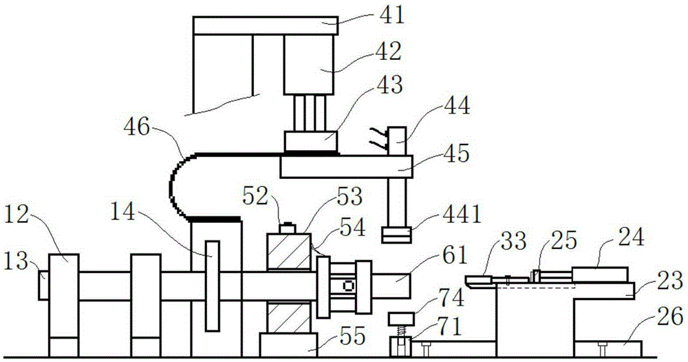
[0036] combine Figure 1 to Figure 7 , a stator shell automatic welding machine in this embodiment includes a control system, a drive mechanism, an element support mechanism, a welding mechanism and a push positioning mechanism, and the drive mechanism includes a motor 11, a bearing seat 12 and a main shaft 13, wherein the motor 11 is a stepping motor, which can accurately control the angular displacement; the main shaft 13 is supported by two parallel bearing housings 12, and the main shaft pulley 14 is installed on the main shaft 13, and the main shaft pulley 14 is output by the power transmission belt and the motor 11. The shafts are connected, the motor 11 controls the rotation of the main shaft 13 through the belt transmission, and the inner ring surface of the transmission belt has stripes to increase the friction to ensure the accuracy of the rotation angle.

[0037] see Figure 6 , the component support mechanism in this embodiment includes a magnetic strip pivot 61, ...

Embodiment 2

[0048] combine Figure 5 , a stator shell automatic welding machine of this embodiment, its basic structure is the same as that of Embodiment 1, the difference is that: the welding machine in this embodiment also includes a pressing mechanism, which includes a pressing plate pillar 51, The first platen beam 52, the upper platen 53, the lower platen 55, the second platen beam 56 and the third cylinder 58, the platen pillar 51 is vertically fixed, the upper end of the platen pillar 51 is hinged with the first platen beam 52, and the first platen The crossbeam 52 can rotate around the hinge shaft, and the other end of the first platen crossbeam 52 is fixed on one side of the upper platen 53 by bolts; the other side of the upper platen 53 is fixedly connected with the second platen crossbeam 56; One end of crossbeam pull rod 57 is hinged, and the lower end of crossbeam pull rod 57 is hinged with the piston rod of the 3rd cylinder 58, then can control upper platen 53 to rotate arou...

Embodiment 3

[0051] The basic structure of the automatic stator shell welding machine of this embodiment is the same as that of Embodiment 2, the difference being that the angle between the chamfering slope 312 and the horizontal plane in this embodiment is 45°. In order to visually detect whether the welding interval angles between different magnetic strips are the same, a pointer 54 is fixed on the side of the upper platen 53 towards the chassis 64, and the tip of the pointer 54 rests on the circumferential surface of the end of the chassis 64. Scale marks are provided on the end peripheral surface of the chassis 64 . Every time a magnetic conductive strip is welded, the motor 11 will automatically rotate a set angle, and the cooperation between the pointer 54 and the dial can reflect the accumulated deviation after multiple uses, so as to adjust the equipment in time.


PUM


Abstract

The invention discloses an automatic welding machine for stator casings, and belongs to the field of motor processing. The automatic welding machine disclosed by the invention comprises a control system, a driving mechanism, an element supporting mechanism, a welding mechanism and an advancing and positioning mechanism, wherein in the driving mechanism, a motor controls a main shaft to rotate through belt transmission; a chassis in the element supporting mechanism is mounted at the outer end of the main shaft; the end part of the chassis is a magnetic conductive strip supporting shaft which is coaxial with the chassis; a stator casing sleeve disc is mounted at the inner end of the magnetic conductive strip supporting shaft in a sleeving manner; the welding mechanism is arranged on the element supporting mechanism; the advancing and positioning mechanism and the main shaft are in corresponding arrangement; during welding, the control system controls the middle part of the advancing and positioning mechanism to slide towards the magnetic conductive strip supporting shaft so as to position the magnetic conductive strip, and the welding mechanism is controlled to perform fixed-point welding. According to the automatic welding machine disclosed by the invention, through the cooperation of the welding mechanism, the advancing and positioning mechanism, and a pressing mechanism, the welding processing of a stator casing is automatically completed, so that the labor strength of workers is reduced, and the welding quality and the processing efficiency are greatly improved.

Description

technical field [0001] The invention relates to the technical field of motor processing, and more specifically relates to an automatic stator shell welding machine. Background technique [0002] The starter is an important part of many vehicles and most machines. Its function is to output power to make the engine run from a standstill. The main function of the starter stator assembly is to generate a magnetic field to drive the rotor to rotate, so the stator assembly is the source of power for the starter and one of the most important components. At present, the stator assembly of a starter is generally composed of a stator casing, a magnetic strip and a winding. A plurality of magnetic strips evenly distributed in the circumferential direction are arranged inside the stator casing, and the magnetic strips are welded to the stator casing. [0003] In the process of processing the stator shell in the prior art, the usual method is to use the clamping tool for positioning, pu...

Claims


Application Information

Patent Timeline
Patent Type & Authority Applications(China)
IPC IPC(8): B23K31/02B23K37/04
CPCB23K31/02B23K37/04
Inventor 张亮生
Owner MAANSHAN HETENG AUTO PARTS
Learn More