
Fixed die push-out device

A technology of ejecting device and fixed mold, which is applied in the field of ejecting mechanism of die-casting molds, can solve the problems of inability to ensure that castings are tightly wrapped on the punch, and the wrapping force is small.

Inactive Publication Date: 2016-01-20
CHONGQING YINGRUISHENG DIE CASTING
View PDF0 Cites 3 Cited by
  • Summary
  • Abstract
  • Description
  • Claims
  • Application Information

AI Technical Summary

Problems solved by technology

[0003] Under normal circumstances, a reasonable mold design should be that the casting is separated from the fixed mold when the mold is opened, wrapped tightly on the movable mold, and returned together with the movable mold, and the casting is ejected through the ejector pin on the ejector mechanism on the side of the movable mold. However, for some castings with special geometric shapes, the surface area of ​​the punch is much smaller than the area of ​​the die, so that the tightening force is too small to ensure that the casting is tightly wrapped on the punch and stays in the fixed mold when the mold is opened. It is necessary to design a push-out mechanism, relying on the thrust of the push-out mechanism to separate the casting from the fixed mold

Method used


Image

  • Fixed die push-out device

Examples


Embodiment Construction

[0014] The present invention will be described in further detail below by means of specific embodiments:

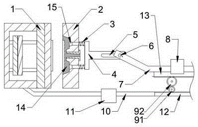
[0015] The reference signs in the drawings of the description include: fixed mold 2, movable mold 1, spring 3, push rod 4, time delay groove 5, driven rod shaft 6, driven rod 7, driven rod guide chute 8, driving rod Gear 91, driven gear 92, driving rod 10, driving rod guide chute 11, driving rack 12, driven rack 13, casting 14, ejection end 15.

[0016] Examples are attached figure 1 Shown: includes fixed mold 2, fixed mold 2 is provided with push rod 4, and push rod 4 is provided with a plurality of ejection ends 15, and each ejection end 15 is provided with spring 3, in order to fix push rod 4 On the fixed mold 2, the other end opposite to the ejection end 15 is provided with a time-delay groove 5, and a driven rod shaft 6 is slidably connected in the time-delay groove 5, and the driven rod shaft 6 is fixed on the driven rod 7. The driven rod 7 is slidably connected i...


PUM


Abstract

The invention discloses a fixed die push-out device. The fixed die push-out device comprises a fixed die. The fixed die is provided with a push rod. The push rod is provided with a plurality of ejecting ends. Springs are arranged at the ejecting ends and used for fixing the push rod to the fixed die. The ejecting ends and the fixed die are in a pressed and sealed state. A delay groove is formed in the power end of the push rod. A driven rod shaft is in sliding connection in the delay groove and is fixed to a driven rod. The driven rod is connected to a drive rod through a gear and rack combination. The drive rod is fixed to the fixed die, and the drive rod moves along with the fixed die. The fixed die push-out device which utilizes die sinking force, and is compact in structure, simple and efficient is provided to achieve the purpose of pushing a casting out of the fixed die according to the casting shape, the technology requirement and other reason requirements.

Description

technical field [0001] The invention relates to the field of die-casting mold ejection mechanisms, in particular to a fixed mold ejection device. Background technique [0002] Die casting is a metal casting process characterized by the use of mold cavities to apply high pressure to molten metal. Molds are usually machined from stronger alloys, a process somewhat similar to injection molding. In each cycle of die-casting, the plastic parts must be accurately released from the die cavity or the core. The device that completes the ejection of the plastic parts is called the demoulding mechanism, also often called the push-out mechanism. The ejection mechanism is generally composed of three major components: ejection, reset and guidance. [0003] Under normal circumstances, a reasonable mold design should be that the casting is separated from the fixed mold when the mold is opened, wrapped tightly on the movable mold, and returned together with the movable mold, and the castin...

Claims


Application Information

Patent Timeline
Patent Type & Authority Applications(China)
IPC IPC(8): B22D17/22
Inventor 王燕
Owner CHONGQING YINGRUISHENG DIE CASTING
Learn More