


Quick Research
Generate reliable direction feasibility study reports for your R&D in just a few steps.

Technical Q&A
Discover and master advanced knowledge NOW. Basics, ideas, possibilities, all at once.

Find Solutions
As an expert in R&D theories, this can generate solutions to your technical problems instantly.

Evaluate Feasibility
Analyze your overall solution with one click, know your potential R&D risks in advance.

Monitor Landscape
Get weekly tech updates, stay abreast of the latest tech innovations and key insights.
Tapping massage fitness chair
A technology of fitness chairs and chairs, which is applied in the direction of roller massage, vibration massage, massage auxiliary products, etc. It can solve the problems of high cost, complex structure, and large volume, and achieve the effects of reducing frictional resistance, simple results, and reducing noise
- Summary
- Abstract
- Description
- Claims
- Application Information
AI Technical Summary
Problems solved by technology
Method used
Image

Examples
Embodiment 1
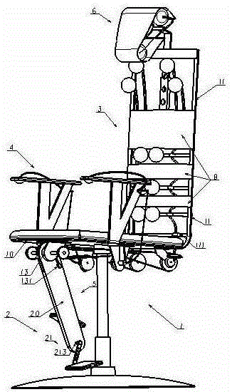
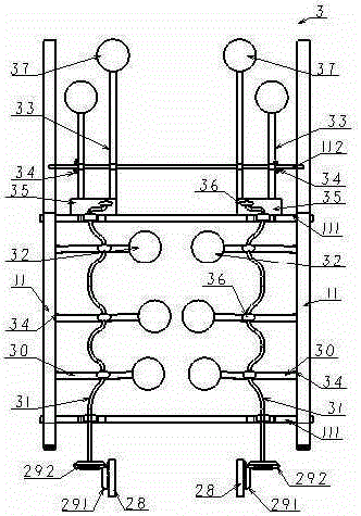
[0024] like figure 1 and 2 As shown, it is a schematic diagram of the overall structure of Embodiment 1 of the present invention, a beat massage fitness chair, comprising: a chair body 1, a driving device 2, and a massage device 3, and is characterized in that the massage device 3 includes: The massage head 32, the hammer rod 30 is connected to the backrest bracket 11, the crankshaft 31 is driven by the driving device 3 to push the hammer rod 30 to swing, the crankshaft 31 is connected to the cross bar 111, and the cross bar 111 is connected to the backrest bracket 11 fixed on the chair body 1 Above, the hammer rod 30 is made of elastic material or a torsional elastic member 34 is set between the hammer rod 30 and the backrest bracket 11, so under the action of the elastic resistance and the push of the crankshaft 31, the hammer rod 30 swings back and forth, driving the massage head 32 to the human body. Beat repeatedly.
[0025] In order to realize the health care function ...
Embodiment 2
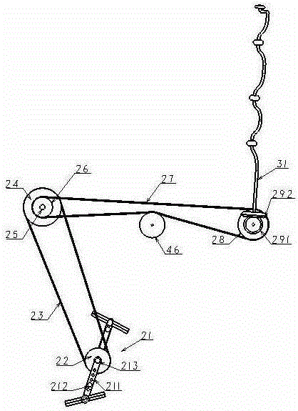
[0031] In addition, if Figure 8 The driving device 2 of the massage device 3 can also be realized by an electric motor 7, the electric motor 7 is arranged at the rear end of the base bracket 10 of the chair body 1, and the crankshaft 31 is driven by the electric motor 7 through the gear set 71 and the bevel gears 291, 292 turn.
[0032] like figure 1 and 8 As shown, the backrest bracket 11 is also provided with a backrest belt 8, which is used to carry part of the abutment force and improve the comfort performance.
[0033] In addition, the massage heads 32, 37 and the armrest massage head 41 are generally made of rubber, plastic, or other flexible materials with high elasticity, and can also be made of wood, bamboo, or metal. The massage head can be smooth or convex grainy.
PUM
 Abstract
Description
Claims
Application Information
 - R&D Engineer
- R&D Manager
- IP Professional
- Industry Leading Data Capabilities
- Powerful AI technology
- Patent DNA Extraction
Browse by: Latest US Patents, China's latest patents, Technical Efficacy Thesaurus, Application Domain, Technology Topic, Popular Technical Reports.
© 2024 PatSnap. All rights reserved.Legal|Privacy policy|Modern Slavery Act Transparency Statement|Sitemap|About US| Contact US: help@patsnap.com