
Branch line coupler and manufacture method thereof

A manufacturing method and coupler technology, applied in the microwave field, can solve the problems of inconvenient connection, lack of common mode suppression ability, and inability to suppress environmental noise well, so as to achieve the effect of suppressing environmental noise

Active Publication Date: 2016-01-13
苏州伟通成电子科技有限公司
View PDF2 Cites 7 Cited by
  • Summary
  • Abstract
  • Description
  • Claims
  • Application Information

AI Technical Summary

Problems solved by technology

The single-ended branch line coupler does not have common mode rejection capability, so it cannot suppress environmental noise well, and it does not have the function of power and phase distribution for differential signals, so it is inconvenient to connect with balanced devices.

Method used


Image

  • Branch line coupler and manufacture method thereof
  • Branch line coupler and manufacture method thereof
  • Branch line coupler and manufacture method thereof

Examples


Embodiment 1

[0050] see figure 1 It is a schematic structural diagram of a branch line coupler according to an embodiment of the present invention. The branch line coupler in the embodiment of the present invention includes: four balanced ports, the first balanced port A, the second balanced port B, the third balanced port C and the fourth balanced port D, each balanced port Both are composed of two single ports, the common mode signal is suppressed, and the differential mode signal needs to meet the same amplitude and 180° phase difference at the ports.

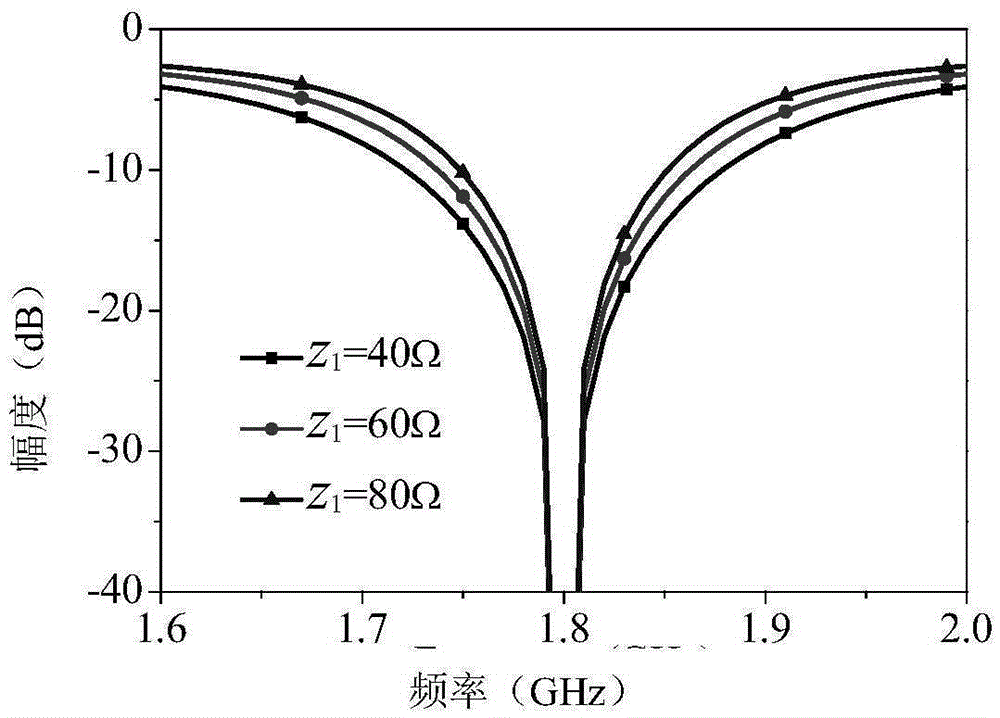
[0051] Specifically, see figure 1 , the first balanced port A includes single port 1 and single port 2, and the passing impedance between single port 1 and 2 is Z 1 The half-wavelength transmission line 10 is connected. The second balanced port B includes single port 3 and single port 4, and the passing impedance between single port 3 and 4 is Z 1 The half-wavelength transmission line 10 is connected. The third balanced port C inclu...

Embodiment 2

[0090] see Figure 8 It is a flowchart of a manufacturing method of a branch line coupler according to an embodiment of the present invention. It includes the following steps:

[0091] S1. Pass the first balanced port and the fourth balanced port through impedance Z 2 A quarter-wavelength transmission line connection;

[0092] S2, passing the first balanced port and the second balanced port through impedance Z 3 A quarter-wavelength transmission line connection;

[0093] S3, passing the second balanced port and the third balanced port through impedance Z 2 A quarter-wavelength transmission line connection;

[0094] S4, passing the third balanced port and the fourth balanced port through an impedance of Z 3 A quarter-wavelength transmission line connection;

[0095] S5. Pass the two single-ports of each balanced port through impedance Z 1 half-wavelength transmission line connection.

[0096] In one embodiment, the method of the embodiment of the present invention also...


PUM

PropertyMeasurementUnit
Electrical lengthaaaaaaaaaa
Thicknessaaaaaaaaaa

Abstract

The invention discloses a branch line coupler and a manufacture method thereof. The branch line coupler comprises a first balanced port, a second balanced port, a third balanced port and a fourth balanced port, wherein the first balanced port is connected with the fourth balanced port via a quarter-wave transmission line with an impedance of Z2; the first balanced port is connected with the second balanced port via a quarter-wave transmission line with an impedance of Z3; the second balanced port is connected with the third balanced port via a quarter-wave transmission line with an impedance of Z2; the third balanced port is connected with the fourth balanced port via a quarter-wave transmission line with an impedance of Z3; each balanced port comprises two single ports; the two single ports of each balanced port are connected via a half-wave transmission line with an impedance of Z1. Beneficial effects of the invention: the branch line coupler has power distribution and phase distribution functions for the differential mode signal and can effectively suppress the common-mode signal.

Description

technical field [0001] The invention relates to the field of microwave technology, and more specifically, to a branch line coupler and a manufacturing method thereof. Background technique [0002] In microwave and millimeter wave commercial and military communication systems, the branch line coupler is an important device in the microwave system. It distributes the amplitude and phase of the microwave signal according to a certain ratio. Branch line couplers are used in balanced amplifiers, microwave network analyzers, automatic gain controls, and power devices in signal generators. And it plays an important role in the microwave components and the whole machine to realize various functions. [0003] Traditional branch line couplers are designed by introducing a quarter-wavelength transmission line, and they are all single-ended designs. The single-ended branch line coupler does not have common-mode rejection capability, so it cannot suppress environmental noise well, and ...

Claims


Application Information

Patent Timeline
IPC IPC(8): H01P5/16
Inventor 施金强俊陈建新秦伟唐慧周立衡包志华
Owner 苏州伟通成电子科技有限公司
Learn More