A distributed photovoltaic roof power generation battery panel structure

A distributed photovoltaic and battery panel technology, applied in the direction of photovoltaic power generation, photovoltaic module support structure, photovoltaic module, etc., can solve problems such as the decline in power generation efficiency of solar panels, flexible adjustment of solar panels, and the impact of solar panel installation. Achieve the effects of simple structure, flexible and convenient use, and improved power generation efficiency

Active Publication Date: 2017-04-26
苏州华安普新能源科技有限公司
View PDF5 Cites 0 Cited by
  • Summary
  • Abstract
  • Description
  • Claims
  • Application Information

AI Technical Summary

Problems solved by technology

[0002] At present, the method of installing solar power generation panels on the roof for photovoltaic power generation has gradually been promoted and popularized, but it has also been found in actual use that when the current solar power generation panels are installed on the roof, mainly through It is carried out with a special positioning frame, but the current positioning frame is often a metal frame structure independent of each other. Although it can meet the needs of positioning the solar panel, it cannot effectively install the solar panel during use. Due to the flexible adjustment of the location, the installation of solar panels is easily affected by the roof structure of the building, and the environmental adaptability is insufficient. Harsh natural environments such as rain, snow, etc. are affected, and lead to a decrease in the power generation efficiency of solar panels and a shortened service life. Therefore, in order to solve this problem, it is urgent to develop an inventive solar panel structure to meet the needs of actual use.

Method used


Image

  • A distributed photovoltaic roof power generation battery panel structure

Examples


Embodiment Construction

[0015] In order to make the technical means, creative features, goals and effects achieved by the present invention easy to understand, the present invention will be further described below in conjunction with specific embodiments.

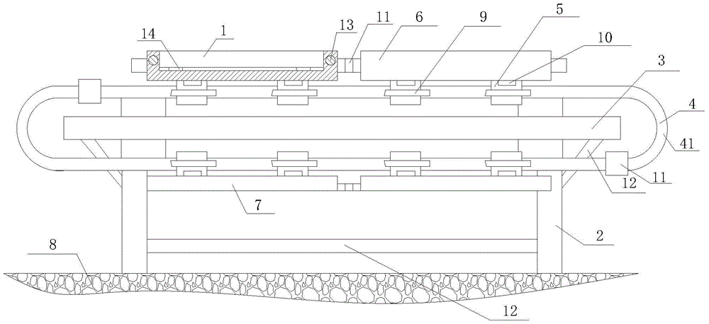
[0016] Such as figure 1 The structure of a distributed photovoltaic roof power generation battery panel group includes a positioning frame and a solar panel 1, and the positioning frame includes a supporting column 2, a supporting frame 3, a positioning guide rail 4, a driving slider 5, a positioning frame 6 and a protective plate 7. The support frame 3 is a rectangular frame structure and is vertically connected to the support column 2. There are at least four support columns 2 and connected to the roof 8 of the building. There are two positioning guide rails 4 and are installed on the support frame 3. The positioning guide rails 4 are all It is a closed ring structure, and the two positioning guide rails 4 are distributed symmetrically with the ...


PUM


Abstract

The invention relates to a distributed photovoltaic roof power generation cell panel assembly structure which comprises a positioning rack and solar cell panels, wherein the positioning rack comprises support vertical posts, a support rack, positioning guide rails, driving sliding blocks, positioning racks and protection plates, wherein the support racks are vertically connected with the support vertical posts, at least four support vertical posts are connected with a building roof, the two positioning guide rails are installed on the support racks, at least one driving sliding block is arranged on each positioning guide rail, the driving sliding blocks are connected with the positioning guide rails by a travelling mechanism in a sliding way, and are hinged with the positioning racks and the protection plates through ratchet mechanisms, the positioning racks and the protection plates are symmetrically distributed around the central line of the positioning guide rails, and the solar cell panels are arranged on the upper surfaces of the positioning racks. By the distributed photovoltaic roof power generation cell panel assembly structure, on one hand, the use number and the layout of the solar cell panels can be flexibly adjusted according to use demands, and on the other hand, the solar cell panels can be effectively protected.

Description

technical field [0001] The invention relates to a photovoltaic power generation device, specifically a distributed photovoltaic roof power generation battery panel structure. Background technique [0002] At present, the method of installing solar power generation panels on the roof for photovoltaic power generation has gradually been promoted and popularized, but it has also been found in actual use that when the current solar power generation panels are installed on the roof, mainly through It is carried out with a special positioning frame, but the current positioning frame is often a metal frame structure independent of each other. Although it can meet the needs of positioning the solar panel, it cannot effectively install the solar panel during use. Due to the flexible adjustment of the location, the installation of solar panels is easily affected by the roof structure of the building, and the environmental adaptability is insufficient. Harsh natural environments such ...

Claims


Application Information

Patent Timeline
Patent Type & Authority Patents(China)
IPC IPC(8): H02S20/23H02S40/10
CPCY02B10/10Y02E10/50
Inventor 顾华顾真郁克文
Owner 苏州华安普新能源科技有限公司
Why Eureka
Try Eureka