Carrier sensing method

A technology of carrier sensing and user equipment, applied in electrical components, wireless communication, network planning, etc., can solve problems such as inability to allocate resources independently, increase hardware complexity, and not be applicable to LTE systems, so as to ensure accuracy and maintain compatibility sexual effect

Active Publication Date: 2015-12-30
ALCATEL LUCENT SHANGHAI BELL CO LTD
View PDF4 Cites 7 Cited by
  • Summary
  • Abstract
  • Description
  • Claims
  • Application Information

AI Technical Summary

Problems solved by technology

However, due to some characteristics of the LTE system itself, the transmitter-based listen-before-send mechanism cannot be applied to the LTE system
First, for the FDD LTE system, the uplink and downlink use different frequency bands, so there is no receiver corresponding to the downlink frequency band on the base station side and no receiver corresponding to the uplink frequency band on the user equipment (userequipment for short UE) side, resulting in If carrier sensing based on the transmitter is to be performed, the radio frequency circuits of the base station and UE must be changed, which greatly increases the complexity of the hardware; secondly, unlike the WiFi system, the LTE system adopts centralized control, and all resources The allocation is done on the base station side, and the UE side cannot allocate resources independently; third, when the coverage of the LTE system overlaps with the coverage of the WiFi system, the carrier sensing results at the transmitter may not truly reflect the receiver’s The actual interference situation, for example, may occur when the base station is located outside the coverage area of ​​the WiFi cell, and the result of listening on the base station side is that an unlicensed frequency band can be used, but the target UE happens to be located within the coverage area of ​​the WiFi cell and happens to Interference with WiFi signals on this frequency band, and vice versa

Method used


Image

  • Carrier sensing method
  • Carrier sensing method
  • Carrier sensing method

Examples


Embodiment Construction

[0038] In the following detailed description of the preferred embodiment, reference is made to the accompanying drawings which form a part hereof. The accompanying drawings show, by way of example, specific embodiments in which the invention can be practiced. The illustrated embodiments are not intended to be exhaustive of all embodiments in accordance with the invention. It is to be understood that other embodiments may be utilized and structural or logical changes may be made without departing from the scope of the present invention. Accordingly, the following detailed description is not limiting, and the scope of the invention is defined by the appended claims.

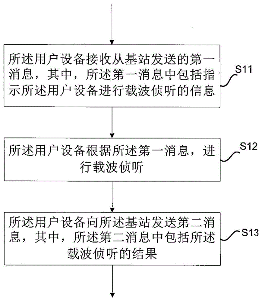
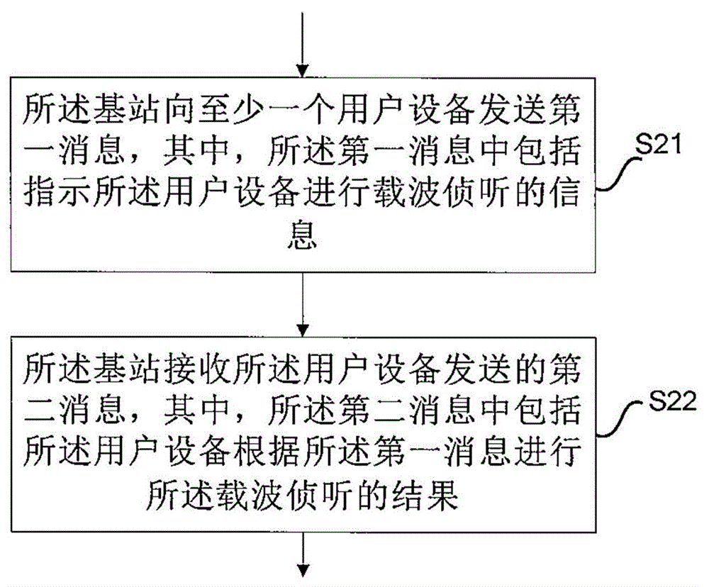
[0039]First, according to the application scenario of the present invention, there is a base station of an LTE communication system, and the base station serves at least one UE. At the same time, there are other carriers within the communication range between the base station and the UE, typically, for example, a...


PUM


Abstract

Provided is a method for carrier sensing on user equipment of an LTE communication system. The method includes: the user equipment receives a first message sent from a base station, wherein the first message comprises information for indicating carrier sensing of the user equipment; the user equipment performs carrier sensing according to the first message; and the user equipment sends a second message to the base station, wherein the second message comprises a result of carrier sensing.

Description

technical field [0001] The present invention relates to the technical field of communication, in particular to the technical field of wireless communication. Background technique [0002] In the field of wireless communication, generally speaking, the traditional deployment method is that the system works in a licensed frequency band (licensed band), that is, the entire spectrum resource is reserved for the system to use. Typically, the LTE communication system works using licensed frequency bands. [0003] However, with the further growth of wireless services, especially wireless data services, the requirements for the capacity and frequency band of the wireless communication system are also increased. In this case, the licensed frequency band resources of the LTE system appear to be relatively insufficient. Therefore, one of the recent research hotspots in the LTE field is how to use unlicensed frequency band resources to offload high-incidence data services. [0004] O...

Claims


Application Information

Patent Timeline
IPC IPC(8): H04W74/08
CPCH04W24/10H04W16/14H04W74/0808
Inventor 刘铮韩锋孟艳
Owner ALCATEL LUCENT SHANGHAI BELL CO LTD
Why Eureka
Try Eureka