
A communication system and energy control device

An energy control and communication system technology, applied in mechanical equipment, electric vehicles, electrical components, etc., can solve the problems of energy waste, communication equipment not having time reporting and charging functions, etc., and achieve the effect of increasing time service and charging

Active Publication Date: 2017-09-01
已达未来(北京)通信科技有限公司
View PDF4 Cites 0 Cited by
  • Summary
  • Abstract
  • Description
  • Claims
  • Application Information

AI Technical Summary

Problems solved by technology

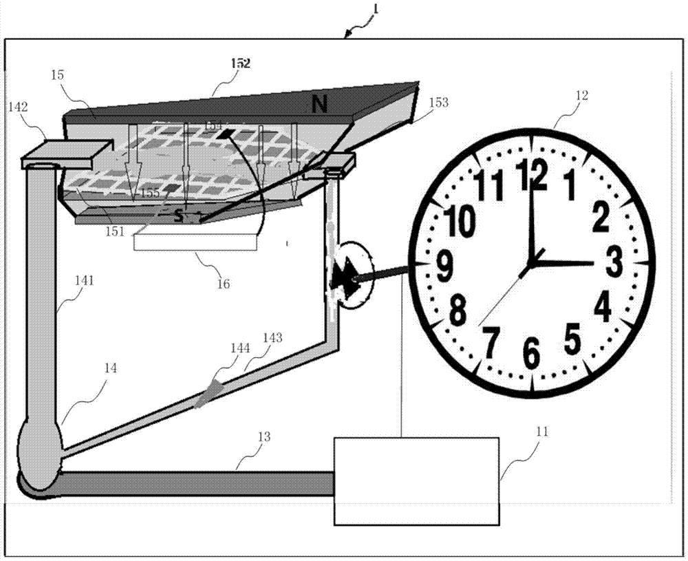
[0005] In view of the above-mentioned shortcomings of the prior art, the purpose of the present invention is to provide a communication system, which is used to solve the problem that the communication system in the prior art generates a large amount of heat energy during operation. At present, this part of heat energy is radiated out through the radiator , but it cannot be fully utilized, causing energy waste to a certain extent, and the existing communication equipment does not have the problem of timekeeping and charging functions

Method used


Image

  • A communication system and energy control device
  • A communication system and energy control device
  • A communication system and energy control device

Examples


Embodiment Construction

[0055] Embodiments of the present invention are described below through specific examples, and those skilled in the art can easily understand other advantages and effects of the present invention from the content disclosed in this specification. The present invention can also be implemented or applied through other different specific embodiments, and various modifications or changes can be made to the details in this specification based on different viewpoints and applications without departing from the spirit of the present invention. It should be noted that, in the case of no conflict, the following embodiments and features in the embodiments can be combined with each other.

[0056] It should be noted that the diagrams provided in the following embodiments are only schematically illustrating the basic ideas of the present invention, and only the components related to the present invention are shown in the diagrams rather than the number, shape and shape of the components in ...


PUM


Abstract

The present invention provides a communication system, comprising: a communication device including a thermal energy generating chip; a clock for timely timing; a heat conduction device for conducting heat energy; a first energy control device for receiving heat energy conducted by the heat conduction The thermal energy heats the conductive fluid inside the first energy control device, driving it to circulate to generate mechanical energy; the second energy control device, connected with the first energy control device, is used to use the conductivity of the conductive fluid to generate electricity for charging peripheral equipment The charging current; the second energy control device includes: a conductive loop part, which flows through the conductive loop part when the conductive fluid flows; a magnetic induction part, which is used to generate a magnetic field covering the conductive loop part, so that the conductive fluid flows through the conductive loop part , an induced current is generated on the conductive loop part. The communication system of the present invention adds the functions of time service and charging to the existing communication system by making full use of the heat energy generated in the working process.

Description

technical field [0001] The invention belongs to the technical field of communication hardware application equipment, and in particular relates to a communication system and energy control equipment. Background technique [0002] The English abbreviation is ICD, and the full name is Industrial Communication Device. It is used for wired communication equipment and wireless communication equipment in industrial control environment. Wired communication equipment is mainly used for serial communication on industrial sites, professional bus communication, industrial Ethernet communication and conversion equipment between various communication protocols, mainly including routers, switches, modems and other equipment. Wireless communication equipment mainly includes wireless AP, wireless bridge, wireless network card, wireless lightning arrester, antenna and other equipment. [0003] In particular, the application of wireless communication equipment. Nowadays, wireless communicat...

Claims


Application Information

Patent Timeline
Patent Type & Authority Patents(China)
IPC IPC(8): H02J7/32F03G7/00
Inventor 吴福健
Owner 已达未来(北京)通信科技有限公司
Learn More