
Charging current control method and device for electric vehicle power battery

A charging current and power battery technology, applied in battery circuit devices, electric vehicles, circuit devices, etc., can solve problems such as overcharge risk of charger response time, influence on estimation accuracy, and bad user experience, so as to avoid overcharge risk, Reduce the impact of estimation accuracy and improve user experience

Active Publication Date: 2018-01-09
BEIJING ELECTRIC VEHICLE
View PDF5 Cites 0 Cited by
  • Summary
  • Abstract
  • Description
  • Claims
  • Application Information

AI Technical Summary

Problems solved by technology

If there is a large difference between the allowable current ranges of two adjacent temperature ranges, the charging current will fluctuate greatly, which will lead to three defects: (1) If the response time of the charger is too long, there will be a risk of overcharging; (2) the current Large jumps will affect the accuracy of SOC estimation; (3) cause bad user experience

Method used


Image

  • Charging current control method and device for electric vehicle power battery
  • Charging current control method and device for electric vehicle power battery
  • Charging current control method and device for electric vehicle power battery

Examples


Embodiment Construction

[0022] Embodiments of the present invention are described in detail below, examples of which are shown in the drawings, wherein the same or similar reference numerals designate the same or similar elements or elements having the same or similar functions throughout. The embodiments described below by referring to the figures are exemplary and are intended to explain the present invention and should not be construed as limiting the present invention.

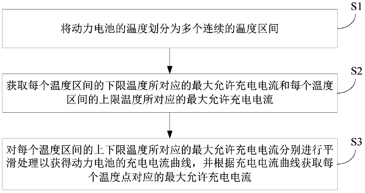
[0023] figure 1 It is a flow chart of a charging current control method for a power battery of an electric vehicle according to an embodiment of the present invention. Such as figure 1 As shown, the charging current control method of the electric vehicle power battery according to the embodiment of the present invention includes the following steps:

[0024] S1, dividing the temperature of the power battery into a plurality of continuous temperature intervals.

[0025] For example, the temperature of the power battery is divid...


PUM


Abstract

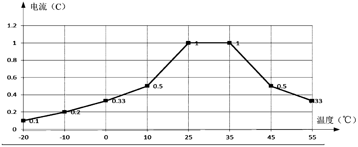
The invention discloses a charging current control method and device for a power battery of an electric vehicle. The method comprises: dividing the temperature of the power battery into a plurality of continuous temperature ranges; obtaining the maximum allowable charge corresponding to the lower limit temperature of each temperature range; The current and the maximum allowable charging current corresponding to the upper limit temperature of each temperature range; the maximum allowable charging current corresponding to the upper and lower limit temperatures of each temperature range are respectively smoothed to obtain the charging current curve of the power battery, and according to the charging current The curve obtains the maximum allowable charging current corresponding to each temperature point. The smoothed current is continuous in any adjacent temperature range, and there will be no large jumps in the allowable charging current caused by the temperature rise or fall during the charging process. This method avoids the impact of the charger on the output The risk of overcharging caused by the long response time of large current adjustments reduces the impact on the accuracy of battery SOC estimation and improves user experience.

Description

technical field [0001] The invention relates to a charging current control method and device for a power battery of an electric vehicle. Background technique [0002] The charging time of electric vehicles is affected by the temperature of the power battery, because the charging current allowed by the power battery changes in different temperature ranges. The charging methods in the related art all need to determine the charging current according to the temperature range of the battery, but it is impossible for the power battery system to test and give the allowable charging current data at all temperature points. If there is a large difference between the allowable current ranges of two adjacent temperature ranges, the charging current will fluctuate greatly, which will lead to three defects: (1) If the response time of the charger is too long, there will be a risk of overcharging; (2) the current Large jumps will affect the accuracy of SOC estimation; (3) cause bad user e...

Claims


Application Information

Patent Timeline
Patent Type & Authority Patents(China)
IPC IPC(8): H02J7/00
Inventor 丑丽丽孟斐
Owner BEIJING ELECTRIC VEHICLE
Learn More