Automatic Pitch Adjustment Mechanism of Vertical Axis Hydrogenerator

A hydroelectric generator, vertical axis technology, applied in the direction of hydroelectric power generation, machine/engine, reaction engine, etc., can solve the problems of large wear of the brake pads, the hydroelectric generator no longer works, etc., to increase the movement resistance and increase the movement water. resistance, the effect of reducing the driving torque

Active Publication Date: 2017-08-22
HANGZHOU HENGLONG NEW ENERGY CO LTD
View PDF6 Cites 0 Cited by
  • Summary
  • Abstract
  • Description
  • Claims
  • Application Information

AI Technical Summary

Problems solved by technology

It solves the problem that in the prior art, when the brake pad is used for braking, the brake pad wears a lot and needs frequent maintenance; and when the manual brake is used, the water flow generator does not work after braking

Method used


Image

  • Automatic Pitch Adjustment Mechanism of Vertical Axis Hydrogenerator
  • Automatic Pitch Adjustment Mechanism of Vertical Axis Hydrogenerator

Examples


Embodiment 1

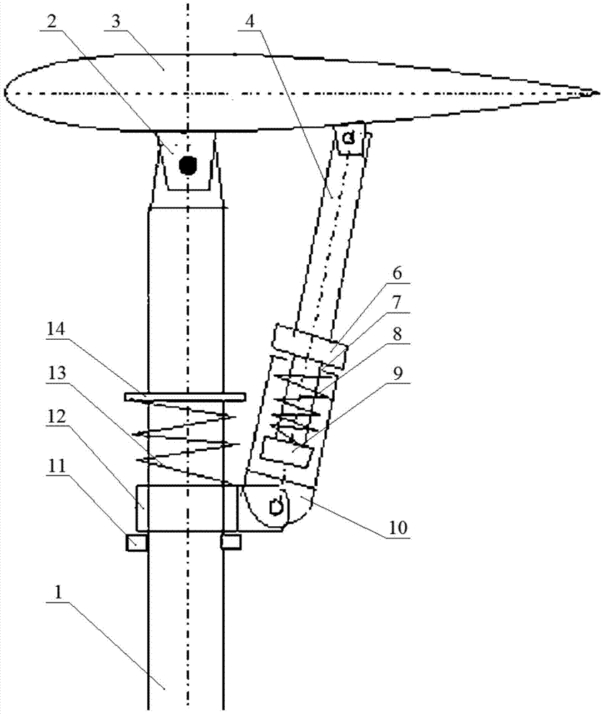
[0038] Such as figure 1 Shown is an automatic pitch-changing mechanism for a vertical-axis hydroelectric generator. The vertical-axis hydroelectric generator includes a main shaft, on which a rotating cylinder (not shown in the figure) is mounted to rotate, and a number of support rods 1 are fixed on the outer wall of the rotating cylinder. , blades 3 are rotated on each support rod, the length direction of the blades is parallel to the axial direction of the main shaft, and the automatic pitch mechanism includes:

[0039] Sliding sleeve 10, one end is hinged on the side wall of support rod 1, and the other end has a through hole 7;

[0040] One end of the speed limiting rod 4 is hinged on the blade 3, the other end passes through the through hole 7, extends into the sliding sleeve 10, and is slidably matched with the sliding sleeve, and the end of the speed limiting rod extending into the sliding sleeve has a first limit bit block 9;

[0041] The first pre-compression sprin...

Embodiment 2

[0047] Such as figure 2 Shown is an automatic pitch-changing mechanism for a vertical-axis hydroelectric generator. The vertical-axis hydroelectric generator includes a main shaft, on which a rotating cylinder (not shown in the figure) is mounted to rotate, and a number of support rods 1 are fixed on the outer wall of the rotating cylinder. , blades 3 are rotated on each support rod, the length direction of the blades is parallel to the axial direction of the main shaft, and the automatic pitch mechanism includes:

[0048] Two fixing rings are fixed on the side wall of the support rod 1 at intervals, and the one adjacent to the blade 3 is the first fixing ring 14, and the one away from the blade is the second fixing ring 11;

[0049] The slider 12 is sheathed on the support rod 1 and is located between two fixing rings, and the slider 12 is slidably matched with the support rod 1;

[0050] The second pre-compression spring 13 is sheathed on the support rod 1, and the two end...


PUM


Abstract

The invention discloses an automatic variable-pitch mechanism of a vertical-axis water flow generator. The vertical-axis water flow generator comprises a main shaft. A rotating cylinder is installed on the main shaft in a rotating mode, a plurality of supporting rods are fixed to the outer side wall of the rotating cylinder, and blades are installed on the supporting rods in a rotating mode. The automatic variable-pitch mechanism comprises sliding sleeves, speed-limiting rods and first pre-compression springs. One end of each sliding sleeve is hinged to the side wall of the corresponding supporting rod, and the other end of each sliding sleeve is provided with a through hole; one end of each speed-limiting rod is hinged to the corresponding blade, and the other ends of the speed-limiting rods penetrate through the through holes to extend into the sliding sleeves and are provided with first limiting blocks. The speed-limiting rods are sleeved with the first pre-compression springs, and the two ends of the first pre-compression springs abut against the first limiting blocks and the sliding sleeves respectively. When the rotating speed of the blades exceeds a critical value, the first pre-compression springs are further compressed, the speed-limiting rods are pulled out of the sliding sleeves and achieve an extension effect, then the angle between the blades and the supporting rods reduces blade driving force and increases blade movement resistance, and accordingly a speed reduction effect is achieved.

Description

technical field [0001] The invention relates to the field of hydraulic generators, in particular to an automatic pitch-changing mechanism of a vertical-axis hydraulic generator. Background technique [0002] A water current generator (referred to as a water machine) is a mechanical device that converts the potential energy of water into electrical energy. The flow of water in oceans, rivers, etc. contains huge energy, and the number of years of its flow time is relatively high. The flow velocity of seawater in ordinary sea areas is mostly 0.5-2m / s, and its energy density is equivalent to wind energy of 4.7m / s-18.7m / s. After it is effectively utilized, the annual available power generation time will be much longer than that of wind power. [0003] Vertical axis hydroelectric generators are attracting more and more attention because of their advantages such as no noise, low start-up flow rate, and no need to adjust the direction of water flow. The speed of the water wheel of...

Claims


Application Information

Patent Timeline
Patent Type & Authority Patents(China)
IPC IPC(8): F03B3/14
CPCY02E10/20
Inventor 戴霓
Owner HANGZHOU HENGLONG NEW ENERGY CO LTD
Why Eureka
Try Eureka