
A railway fastener removal device and its working method

A technology of railway fasteners and fasteners, which is applied to roads, laying tracks, tracks, etc., can solve problems such as low work efficiency, high labor intensity, and many operators, so as to improve construction work efficiency, improve work safety, and work The effect of principle science

Active Publication Date: 2017-03-15
ZHUZHOU TIMES ELECTRONICS TECH CO LTD
View PDF5 Cites 3 Cited by
  • Summary
  • Abstract
  • Description
  • Claims
  • Application Information

AI Technical Summary

Problems solved by technology

In the prior art, either the internal combustion wrench or the electric wrench can only be used to complete a single operation of loosening the nuts on the fasteners, and the whole set of fasteners is usually composed of nuts, washers, spring bars and iron backing plates. Later, washers, bounces, and iron backing plates can only be picked up and removed by another worker
Therefore, the removal of the whole set of fasteners still needs to be manually operated.
[0003] The existing technology adopts the method of manual operation, and its technical defect is obvious, that is, the operator needs to walk on the railway line, hold a heavy internal combustion wrench or an electric wrench on the railway line, and some even carry out fasteners on the bottom of the vehicle. The action of dismantling, picking up and dismantling needs to be bent down. Manual dismantling is labor-intensive, low-efficiency, and highly dangerous, which is not conducive to the current requirements of fast, efficient and safe railway construction.
At the same time, due to the low efficiency of the operation mode of the prior art and the need for many operators, it cannot meet the requirements of rapid construction of the railway skylight point

Method used


Image

  • A railway fastener removal device and its working method
  • A railway fastener removal device and its working method
  • A railway fastener removal device and its working method

Examples


Embodiment Construction

[0027] In order to make the purpose, technical solutions and advantages of the embodiments of the present invention more clear, the technical solutions in the embodiments of the present invention will be clearly and completely described below in conjunction with the drawings in the embodiments of the present invention. Apparently, the described embodiments are only some of the embodiments of the present invention, not all of them. Based on the embodiments of the present invention, all other embodiments obtained by persons of ordinary skill in the art without creative efforts fall within the protection scope of the present invention.

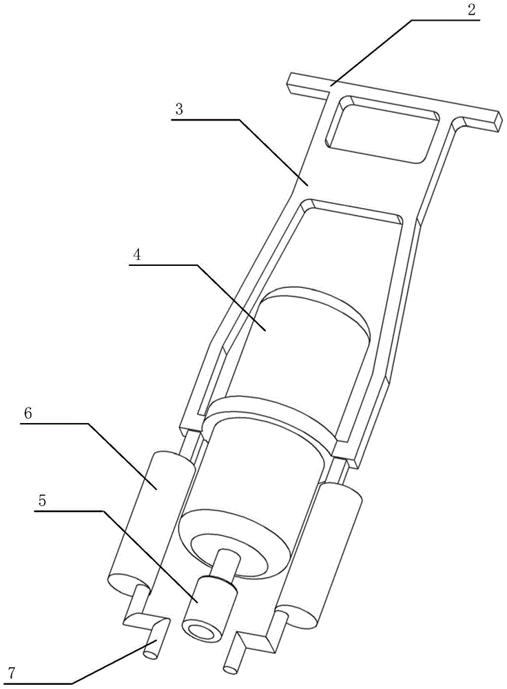
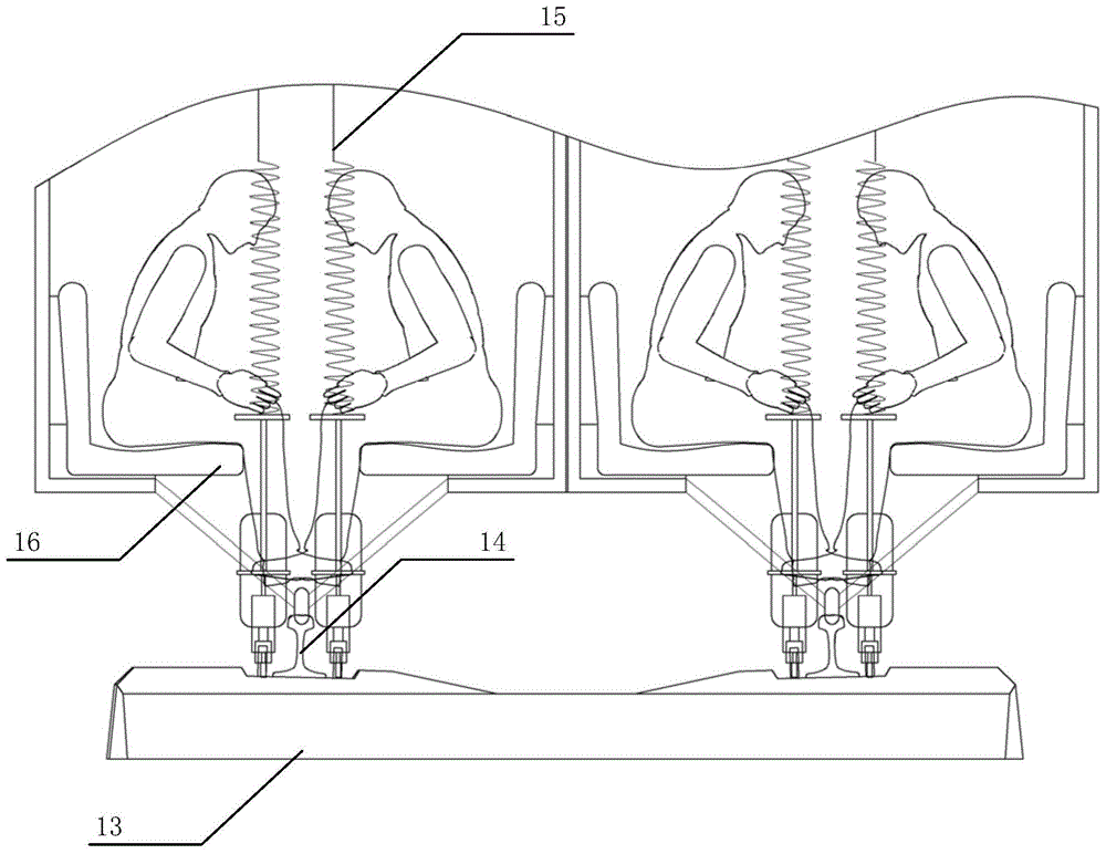
[0028] as attached figure 1 to attach image 3 As shown, the specific embodiments of the railway fastener removal device and the working method thereof of the present invention are provided, and the present invention will be further described below in conjunction with the accompanying drawings and specific embodiments.

[0029] as attached fig...


PUM


Abstract

The invention discloses a railway fastener dismantling device and an operating method thereof. The device is used for dismantling a fastener on a railway line, and comprises a support, an electric wrench, a sleeve and electromagnets, wherein handles are arranged on two sides of the upper part of the support, the electric wrench is fixed at the lower part of the support, the sleeve is connected with the lower part of the electric wrench, and the electromagnets are arranged on two sides of the support. A nut on the fastener is loosened by the electric wrench, the whole fastener is sucked up by magnetic poles at the bottoms of the electromagnets, and the fastener is enabled to automatically fall off after the electromagnets are powered off and demagnetized. According to the device and the operating method thereof, not only can the nut be dismantled, but also the whole fastener can be dismantled; not only is the labor cost reduced, but also the operation efficiency is improved at the same time.

Description

technical field [0001] The invention relates to the field of railway engineering operations, in particular to a railway fastener removal device and an operating method applied in the field of railway engineering operations and maintenance. Background technique [0002] At present, during railway construction operations, it is often necessary to remove fasteners on the line. In the prior art, when workers walk on the railway line, they usually use an internal combustion wrench or an electric wrench to remove the fastener. In the prior art, either the internal combustion wrench or the electric wrench can only be used to complete a single operation of loosening the nuts on the fasteners, and the whole set of fasteners is usually composed of nuts, washers, spring bars and iron backing plates. Later, washers, springs, and iron backing plates can only be picked up and removed by another worker. Therefore, the removal of the whole set of fasteners still needs to be manually opera...

Claims


Application Information

Patent Timeline
Patent Type & Authority Patents(China)
IPC IPC(8): E01B29/24
Inventor 李石平向涌王琰王华刘莎
Owner ZHUZHOU TIMES ELECTRONICS TECH CO LTD
Learn More