
A cylinder head and method for visualizing flow field in a large diesel engine

A technology for visualizing cylinders and internal flow fields, applied to cylinder heads, cylinders, mechanical equipment, etc., can solve the problems that large diesel engines are not easy to realize

Inactive Publication Date: 2018-01-02
SOUTH CHINA UNIV OF TECH
View PDF4 Cites 0 Cited by
  • Summary
  • Abstract
  • Description
  • Claims
  • Application Information

AI Technical Summary

Problems solved by technology

For the diesel engine experiment platform, the optical engine is usually modified or a constant volume incendiary bomb is used to conduct experiments in combination with the optical path system and data acquisition and control system. For the optical engine modification, an extended body is usually added between the body and the cylinder head And the extended piston, a transparent window as large as possible is designed on the upper part of the extended piston, so as to observe the fuel spray, mixing, ignition and combustion process. This modification method is obviously not easy to realize for large diesel engines

Method used


Image

  • A cylinder head and method for visualizing flow field in a large diesel engine
  • A cylinder head and method for visualizing flow field in a large diesel engine
  • A cylinder head and method for visualizing flow field in a large diesel engine

Examples


Embodiment

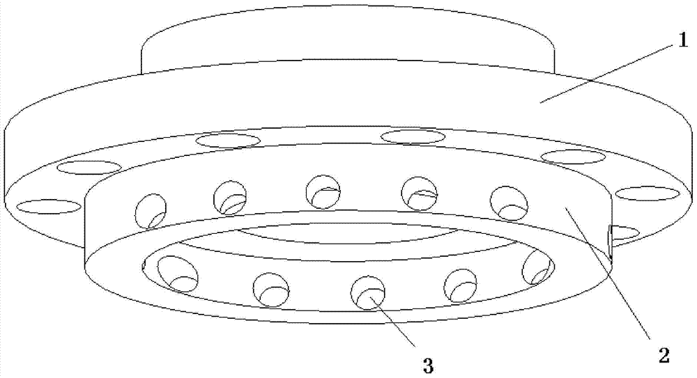
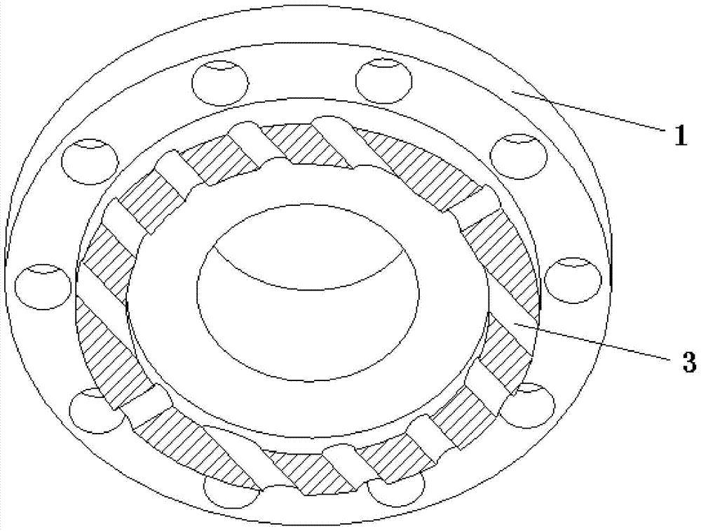
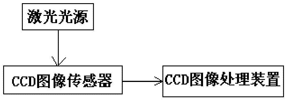
[0022] Such as Figures 1 to 3 shown. The present invention is a visual cylinder head of flow field in a large diesel engine cylinder, comprising a cylinder head body, the cylinder head body includes a cylinder head 1, and the cylinder head 1 has an annular inner edge 2; radially symmetrical openings are arranged on the peripheral wall of the annular inner edge 2 Multiple pairs of through holes 3, and a laser light source is installed in one of the through holes 3, the laser light source is used to collect the information of the flow field in the cylinder during the fuel injection process, and a CCD image sensor is installed in the through hole 3 on the opposite side of the laser light source , the CCD image sensor is used to receive the information of the flow field in the cylinder sent by the laser light source, and transmit the information to the external CCD image processing device for processing;

[0023] Seal the through hole 3 that is not installed with the laser light...


PUM


Abstract

The invention discloses a cylinder head and a method for visualizing the flow field in a cylinder of a large diesel engine. The cylinder head has an annular inner edge; a plurality of pairs of through holes are arranged radially and symmetrically on the peripheral wall of the annular inner edge, and one of the through holes A laser light source is installed. The laser light source is used to collect the information of the in-cylinder flow field during the fuel injection process. A CCD image sensor is installed in the through hole opposite to the laser light source. The CCD image sensor is used to receive the in-cylinder flow information sent by the laser light source. flow field information, and transmit the information to an external CCD image processing device for processing; on the opposite side where the laser light source is placed, one or two (or more) through holes with different angles can be arbitrarily selected to place the CCD image sensor, so that the CCD image sensor can be placed from The flow field in the cylinder can be observed from multiple angles to improve the accuracy of the analysis. For other through-holes that are not used temporarily, seal and fill them with metal plugging parts to prevent impact on fuel combustion.

Description

technical field [0001] The invention relates to the observation of the flow field in the cylinder of a diesel engine, in particular to a cylinder head and a method for visualizing the flow field in the cylinder of a large diesel engine. Background technique [0002] In recent years, diesel engines have been widely used due to their high power and high efficiency, especially in the field of nautical ships, and have made great contributions to the development of human society and the progress of navigation. During the working process of the diesel engine, the fuel is actually sprayed and diffused in the combustion chamber to generate power. The atomization process of fuel depends not only on the interaction between the gas outside the injection hole and the oil beam, but also on the condition of the flow field in the cylinder and the flow state of the fuel in the injection hole. During the fuel atomization combustion process, due to the influence of many factors, it has varia...

Claims


Application Information

Patent Timeline
Patent Type & Authority Patents(China)
IPC IPC(8): F02F1/24G01M15/02
Inventor 谢小鹏黄恒刘鑫
Owner SOUTH CHINA UNIV OF TECH
Learn More