
Electric derailer and train rail

A derailer, electric technology, applied in the field of derailer, can solve the problem that the electric derailer is difficult to ensure the derailment accuracy, and achieve the effect of ensuring the derailment accuracy, ensuring the safety of life, and improving the safety factor

Active Publication Date: 2015-12-23
武汉迪昌科技有限公司
View PDF5 Cites 3 Cited by
  • Summary
  • Abstract
  • Description
  • Claims
  • Application Information

AI Technical Summary

Problems solved by technology

[0003] The purpose of the present invention is to provide an electric derailer, which aims to solve the problem that the existing electric derailer is difficult to ensure the derailment accuracy when wear occurs

Method used


Image

  • Electric derailer and train rail
  • Electric derailer and train rail
  • Electric derailer and train rail

Examples


Embodiment Construction

[0022] The following will clearly and completely describe the technical solutions in the embodiments of the present invention with reference to the accompanying drawings in the embodiments of the present invention. Obviously, the described embodiments are only some, not all, embodiments of the present invention. Based on the embodiments of the present invention, all other embodiments obtained by persons of ordinary skill in the art without making creative efforts belong to the protection scope of the present invention.

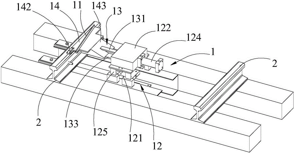
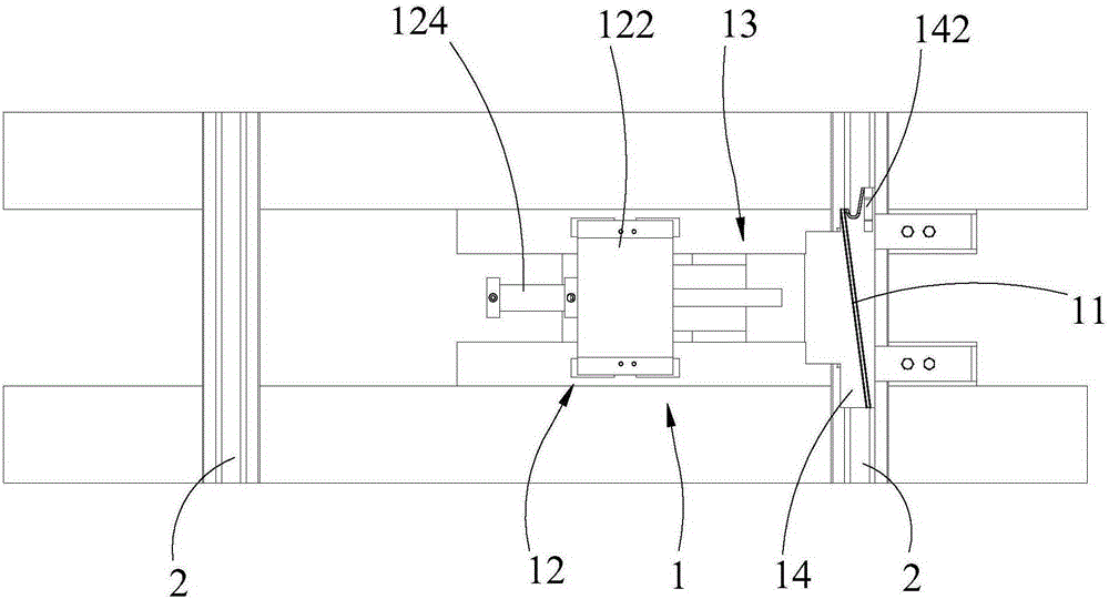
[0023] see Figure 1-Figure 3 , the embodiment of the present invention provides an electric derailer, including a guide plate 11, which can be installed on one of the guide rails 2 for vehicles to run, and usually the track for vehicles to run includes two opposite guide rails 2, The guide plate 11 can be installed on one of the guide rails 2, and the guide plate 11 is inclined along the inboard of the guide rail 2 (between the two guide rails 2) along the tr...


PUM


Abstract

The invention relates to derailers and provides an electric derailer. The electric derailer comprises a guide plate which is installed on one of guide rails used for allowing a train to travel thereon. The guide plate inclines towards the inner side of the guide rail in the traveling direction of the train. The electric derailer further comprises an installing rack and a connecting rack, wherein the installing rack and the guide plate are arranged in a spaced mode, and the installing rack and the guide plate are connected through the connecting rack. The installing rack comprises a base which can be arranged on the ground and a movable seat which is located over the base. The movable seat is fixedly connected with the guide plate through the connecting rack. A first hydraulic cylinder capable of driving the movable seat to move in the vertical direction is arranged between the base and the movable seat. The invention further provides a train rail which comprises the derailer. According to the derailer, the train can be derailed from the guide rails through the guide plate, and the effect of derailing is achieved; in addition, under the action of the first hydraulic cylinder, derailing accuracy can be guaranteed by the derailer under the condition that the guide rails are abraded. The safety coefficient of the train rail during train overhaul is quite high by applying the derailer to the train rail.

Description

technical field [0001] The invention relates to a derailer, in particular to an electric derailer and a train track. Background technique [0002] As the train travels for a long time, the wheels and guide rails will be consumed due to wear and tear, and the accuracy of the electric derailer will decrease, resulting in the derailment function of the derailer to derail the train. There is a threat to personal safety. Contents of the invention [0003] The object of the present invention is to provide an electric derailer, which is intended to solve the problem that the existing electric derailer is difficult to ensure derailment accuracy when wear occurs. [0004] The present invention is achieved like this: [0005] The invention provides an electric derailer, which includes a guide plate that can be installed on one of the guide rails for vehicles to run, the guide plate is inclined to the inner side of the guide rail along the vehicle running direction, and also includ...

Claims


Application Information

Patent Timeline
Patent Type & Authority Applications(China)
IPC IPC(8): B61K5/06
Inventor 寇振华符武军王磊周颜红
Owner 武汉迪昌科技有限公司
Learn More