
Foam sticking machine and processing technology adopting same

A pasting machine and foam technology, applied to layered products, lamination devices, lamination, etc., can solve the problems of inaccurate pasting position, low work efficiency, poor pasting quality, etc., and achieve good pasting quality and convenient feeding And the effect of safety and simple structure

Inactive Publication Date: 2015-12-23
JIANGSU BVM INTELLIGENT TECH
View PDF6 Cites 2 Cited by
  • Summary
  • Abstract
  • Description
  • Claims
  • Application Information

AI Technical Summary

Problems solved by technology

The patent with authorized notification number CN102689485B discloses a pearl cotton electric heating automatic sticking machine, which includes an area corresponding to the vertical position and an upper material adsorption device. The lower part of the pearl cotton material is placed in the area, and the upper part of the pearl cotton material is placed in the lower part. On the one hand, feeding is troublesome and difficult to align, making the sticking position inaccurate and the sticking quality poor. If the upper needle-shaped adsorption device and the lower needle-shaped adsorption device are suddenly activated during the feeding process, they will touch the hands of the operator. Unloading is very unsafe, and the material cannot be loaded during the processing of the upper and lower parts of the pearl cotton material. It is necessary to wait for the equipment to stop before placing the next upper and lower material, which is inefficient.

Method used


Image

  • Foam sticking machine and processing technology adopting same
  • Foam sticking machine and processing technology adopting same
  • Foam sticking machine and processing technology adopting same

Examples


Embodiment Construction

[0030] The present invention will now be further described in detail in conjunction with the accompanying drawings and embodiments. These drawings are all simplified schematic diagrams, only illustrating the basic structure of the present invention in a schematic manner, so it only shows the composition related to the present invention.

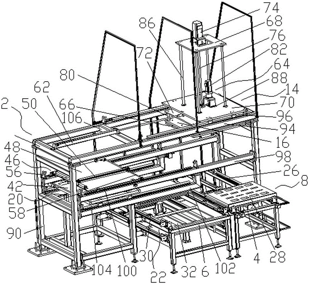
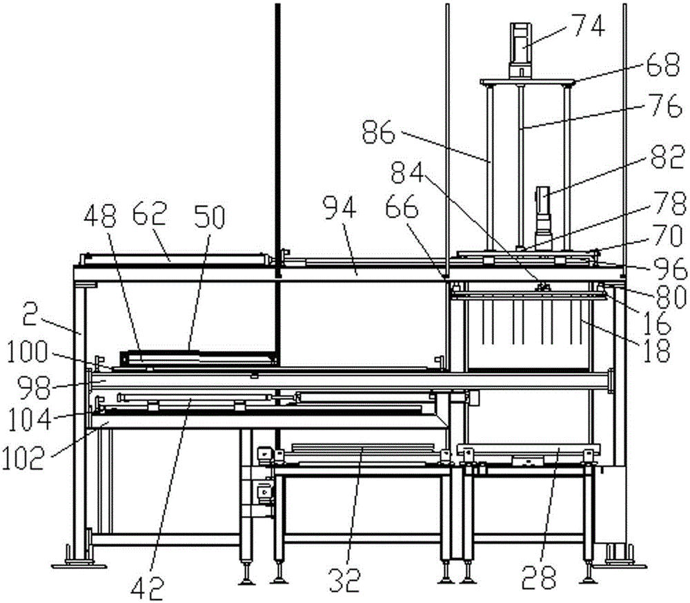
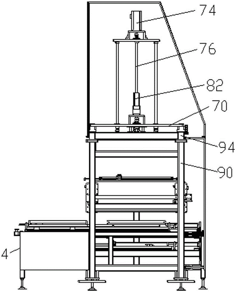
[0031] Such as figure 1 As shown, a foam pasting machine includes a frame 2 and a control device (not shown in the figure), and also includes a first discharge rack 4 and a second discharge rack 6; the first discharge rack 4 and the second discharge rack At least one of the discharging racks 6 is at least partly located on the outside of the frame 2, and is provided with a reciprocating first feeding mechanism 8, and the first feeding mechanism 8 is driven by the first drive mechanism 10 to and from the first discharging mechanism outside the frame 2. material position (not shown in the figure) and the first working position in the frame 2 (n...


PUM


Abstract

The invention relates to a foam sticking machine which comprises a rack, a control device, a first loading rack and a second loading rack, wherein at least part of at least one of the first loading rack and the second loading rack is located on the outer side of the rack, and a first material feeding mechanism with a reciprocating characteristic is arranged and driven by a first driving mechanism to reciprocate between a first loading position outside the rack and a first working position in the rack; a material taking mechanism capable of moving horizontally is arranged on the rack, a needle plate capable of moving vertically is arranged on the material taking mechanism, and a plurality of needles are arranged on the needle plate; an electrical heating mechanism is arranged on the rack; based on input parameters or instructions, the control device controls the sticking machine to work. The invention further relates to a processing technology adopting the foam sticking machine. The foam sticking machine and the processing technology adopting the same have the benefits that the structure is simple, the use is convenient, loading is convenient and safe, the machine can perform loading continuously during operation, the sticking work efficiency is greatly improved, the requirement for big batch of foam sticking is met, the sticking quality is good, and the enterprise competitiveness is high.

Description

technical field [0001] The invention relates to a pasting machine, in particular to a foam pasting machine and its processing technology. Background technique [0002] Foam is used as a shock-proof cushioning material because of its elasticity, freedom of bending, light weight, and ease of use. It is widely used in the packaging of electronic products such as televisions and computers. The patent with authorized notification number CN102689485B discloses a pearl cotton electric heating automatic sticking machine, which includes an area corresponding to the vertical position and an upper material adsorption device. The lower part of the pearl cotton material is placed in the area, and the upper part of the pearl cotton material is placed in the lower part. On the one hand, feeding is troublesome and difficult to align, making the sticking position inaccurate and the sticking quality poor. If the upper needle-shaped adsorption device and the lower needle-shaped adsorption devi...

Claims


Application Information

Patent Timeline
Patent Type & Authority Applications(China)
IPC IPC(8): B32B37/00B32B37/06B32B37/12B32B37/10
CPCB32B37/06B32B37/10B32B37/0046B32B37/12
Inventor 黄先刚
Owner JIANGSU BVM INTELLIGENT TECH
Learn More