
A corrugated pin electro-optic modulator structure

An electro-optical modulator and wave-like technology, applied in instruments, optics, nonlinear optics, etc., can solve problems such as device heating, increase junction area, improve carrier injection concentration, and facilitate electro-optical modulation.

Inactive Publication Date: 2018-05-18
XI'AN POLYTECHNIC UNIVERSITY
View PDF2 Cites 0 Cited by
  • Summary
  • Abstract
  • Description
  • Claims
  • Application Information

AI Technical Summary

Problems solved by technology

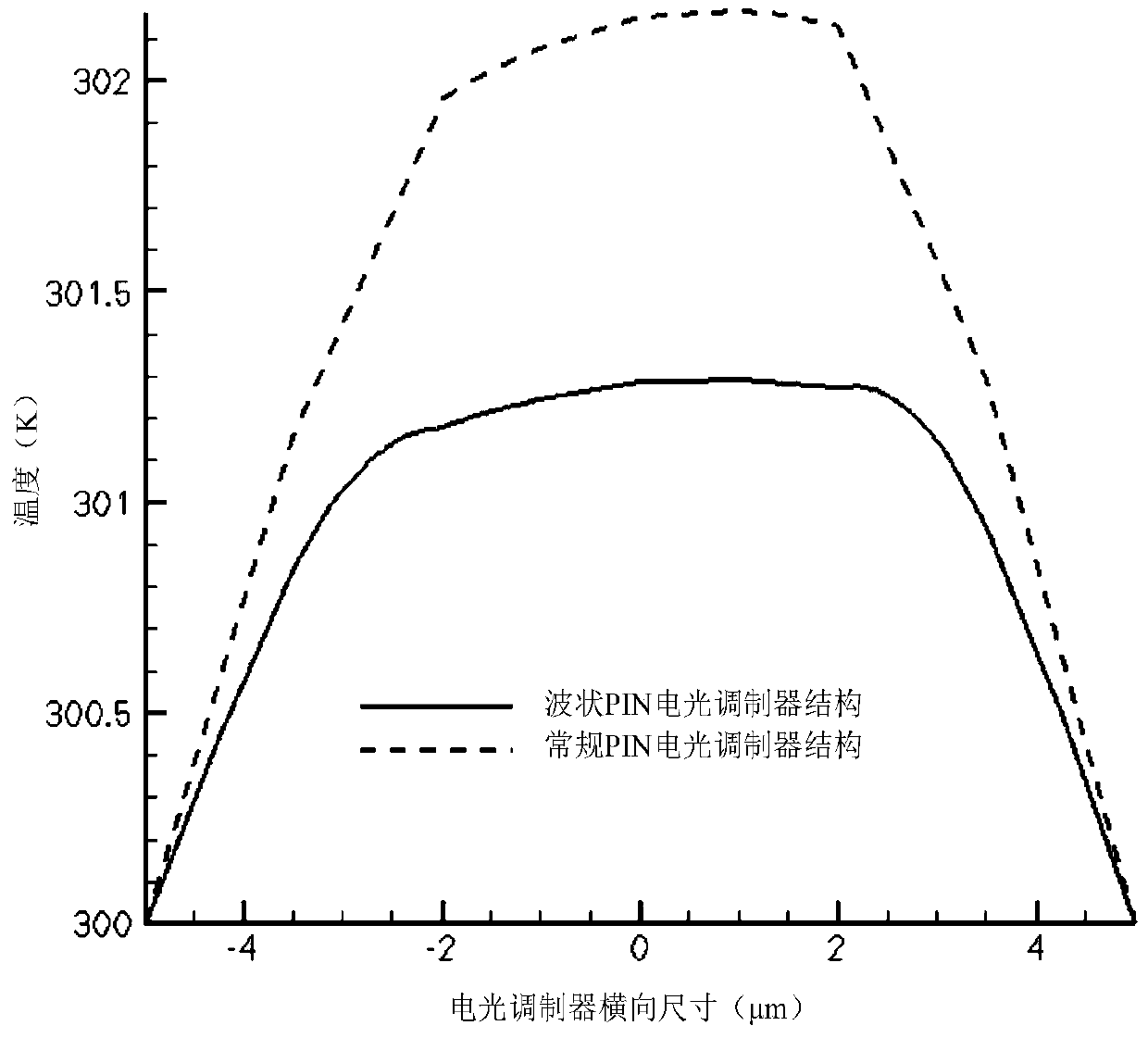
In addition, the PIN structure also has the characteristics of simple structure, fast modulation speed and easy process realization. Today, the PIN structure has been widely used in the design of semiconductor electro-optic modulators, but because the PIN structure is very sensitive to changes in the refractive index, When the device undergoes electro-optic modulation, the device will heat up due to the injection of current, and the change of the refractive index by the thermo-optic effect is just opposite to the plasmonic dispersion effect, which inhibits the electro-optic modulation.

Method used


Image

  • A corrugated pin electro-optic modulator structure
  • A corrugated pin electro-optic modulator structure
  • A corrugated pin electro-optic modulator structure

Examples


Embodiment Construction

[0025] The present invention will be described in detail below in conjunction with the accompanying drawings and specific embodiments.

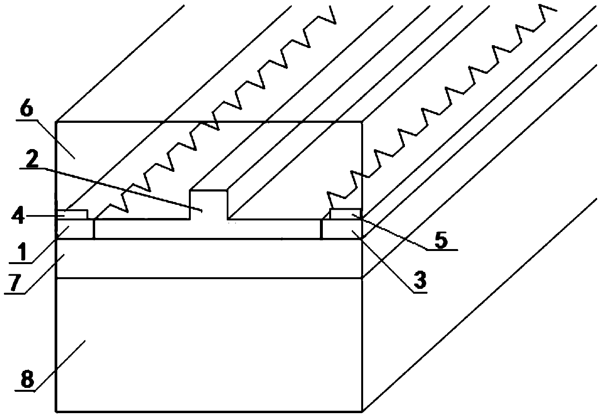
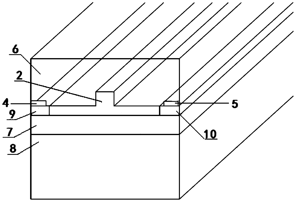
[0026] A kind of corrugated PIN electro-optic modulator structure of the present invention, its structure is as follows figure 1 As shown, it includes an N-Sub type substrate 8, and the upper part of the N-Sub type substrate 8 is provided with SiO 2 Buried layer 7, SiO 2 Both sides of the upper part of the buried layer 7 are respectively provided with a corrugated P+ well region 1, a corrugated N+ well region 3, SiO 2 An intrinsic N-type modulation region 2 is arranged between the wavy P+ well region 1 and the wavy N+ well region 3 on the upper part of the buried layer 7, the first electrode 4 is arranged on the upper part of the wavy P+ well region 1, and the upper part of the wavy N+ well region 3 The second electrode 5 is arranged, and the upper part of the first electrode 4, the intrinsic N-type modulation region 2 and the second electr...


PUM

PropertyMeasurementUnit
heightaaaaaaaaaa
widthaaaaaaaaaa
widthaaaaaaaaaa

Abstract

The invention discloses a corrugated PIN electro-optic modulator structure which comprises an N-Sub type substrate. The upper portion of the N-Sub type substrate is provided with a SiO2 buried layer, a corrugated P+ well region and a corrugated N+ well region are arranged on the two sides of the upper portion of the SiO2 buried layer respectively, an intrinsic N type modulation area is arranged between the corrugated P+ well region and the corrugated N+ well region on the upper portion of the SiO2 buried layer, a first electrode is arranged on the upper portion of the corrugated P+ well region, and a second electrode is arranged on the upper portion of the corrugated N+ well region. A SiO2 covering layer covers the upper portions of the first electrode, the intrinsic N type modulation area and the second electrode. According to the corrugated PIN electro-optic modulator structure, the heating of a PIN electro-optic modulator is effectively reduced, and the influence of the thermo-optic effect on the PIN electro-optic modulator is restrained; furthermore, the high carrier injection is achieved, and the plasma dispersion effect is enhanced.

Description

technical field [0001] The invention belongs to the technical field of optoelectronic devices, and in particular relates to a corrugated PIN electro-optical modulator structure. Background technique [0002] The PIN electro-optic modulator is a silicon-based electro-optic modulator that uses the plasma dispersion effect to change the refractive index of the intrinsic modulation region in the PIN structure. [0003] In recent years, with the advancement of optoelectronic technology, silicon-based modulators have entered micro-nano dimensions. Silicon-based electro-optic modulators can transmit single-mode light waves, and have the advantages of high speed, low loss and small size, and are compatible with integrated circuit manufacturing processes. Compatible, has now become the core of silicon-based optoelectronic devices. [0004] The plasmonic dispersion effect is to change the free carrier concentration in the optical waveguide, thereby causing the change of the refractiv...

Claims


Application Information

Patent Timeline
Patent Type & Authority Patents(China)
IPC IPC(8): G02F1/015
CPCG02F1/015G02F1/0151
Inventor 冯松薛斌李连碧雷倩倩宋立勋翟学军朱长军
Owner XI'AN POLYTECHNIC UNIVERSITY
Learn More