Imaging lens, iris imaging module and iris recognition device

An imaging lens and lens technology, which is applied in the field of biometrics, can solve the problems of large volume of zoom optical system, unfavorable grasp of distance and alignment, narrow collection range, etc., and achieve high imaging quality, simple structure, and wide collection range.

Active Publication Date: 2017-09-12
BEIJING EYECOOL TECH CO LTD +1
View PDF8 Cites 0 Cited by
  • Summary
  • Abstract
  • Description
  • Claims
  • Application Information

AI Technical Summary

Problems solved by technology

At present, the existing iris collection optical system can be divided into: zoom optical system and fixed focus optical system, among which the zoom optical system is large in size, complex in structure, high in cost and difficult to assemble; the fixed focus optical system is simple in structure, low in cost and convenient to install At present, the products on the market generally use fixed-focus optical systems, but most of the existing fixed-focus optical systems are monocular acquisition optical systems, which are generally equipped with image sensors with lower pixels (VGA is enough)
[0003] However, the acquisition of one eye requires a high degree of cooperation from the user, and the acquisition range (depth of field) of the equipment is very narrow, which is extremely inconvenient to use and is not conducive to grasping the distance and alignment

Method used


Image

  • Imaging lens, iris imaging module and iris recognition device
  • Imaging lens, iris imaging module and iris recognition device
  • Imaging lens, iris imaging module and iris recognition device

Examples


Embodiment 1

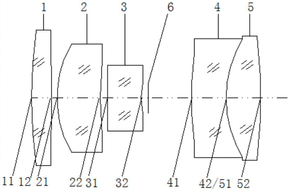
[0043] This embodiment is an imaging lens for binocular iris recognition, such as figure 2As shown, it is composed of five lens groups and a diaphragm 6'. An image sensor 8' is arranged behind the imaging lens. Along the incident direction of light, there are: a first lens 1' with positive refractive power, which is a biconvex lens. The front surface 11' is convex and the back surface 12' is convex; the second lens 2' having positive power is a convex-concave lens with a front surface 21' being convex and a back surface 22' being concave; having negative power The third lens 3' is a convex-concave lens, its front surface 31' is a convex surface, and its rear surface 32' is a concave surface; the fourth lens 4' and the fifth lens 5' are cemented lenses, and the fourth lens 4' has a positive light A convex-concave lens with a focal power, the front surface 41' is convex, and the back surface 42' is concave; the fifth lens 5' is a biconvex lens with positive power, the front sur...

Embodiment 2

[0050] This embodiment is an imaging lens for binocular iris recognition, such as Figure 4 As shown, it is composed of five lens groups, a diaphragm 6" and a flat filter 7". The rear of the imaging lens is provided with an image sensor 8". , which is a biconvex lens, its front surface 11 "is a convex surface, and its back surface 12" is a convex surface; the second lens 2 "with positive refractive power is a convex-concave lens, its front surface 21 "is a convex surface, and its back surface 22 "is Concave surface; the third lens 3 " with negative power, which is a convex-concave lens, its front surface 31 " is a convex surface, and the rear surface 32 " is a concave surface; the fourth lens 4 " and the fifth lens 5 " are cemented lenses, the first The four lens 4 "is a convex-concave lens with positive refractive power, its front surface 41 "is a convex surface, and its rear surface 42 "is a concave surface; the fifth lens 5 "is a biconvex lens with positive refractive power...


PUM


Abstract

The invention discloses an imaging lens, an iris imaging module and an iris recognition device, which belong to the field of biometric identification. The imaging lens sequentially includes: a first lens from front to back along the light incident direction, and the first lens is a biconvex lens with positive refractive power , the front surface is convex and the back surface is convex; the second lens, the second lens is a convex-concave lens with positive power, the front surface is convex, and the back surface is concave; the third lens, the third lens is a negative light Convex-concave lens with focal power, its front surface is convex, and its back surface is concave; the fourth lens, the fourth lens is a convex-concave lens with positive power, its front surface is convex, and its back surface is concave; The lens is a biconvex lens with positive refractive power, its front surface is convex, and its back surface is convex; the fourth lens and the fifth lens are glued together. The imaging lens of the invention has good imaging quality, wide acquisition range, convenient use, simple structure, convenient assembly and low manufacturing cost.

Description

technical field [0001] The invention relates to the field of biological identification, in particular to an imaging lens, an iris imaging module and an iris identification device. Background technique [0002] Iris recognition is a biometric technology that authenticates user identity based on processing the iris texture information of the eye in an area smaller than 10 mm. The difficulty in realizing this technology lies in how to collect clear and high-quality iris images, that is, high-quality iris image collection optical systems. At present, the existing iris collection optical system can be divided into: zoom optical system and fixed focus optical system, among which the zoom optical system is large in size, complex in structure, high in cost and difficult to assemble; the fixed focus optical system is simple in structure, low in cost and convenient to install At present, the products on the market generally use fixed-focus optical systems, but most of the existing fix...

Claims


Application Information

Patent Timeline
Patent Type & Authority Patents(China)
IPC IPC(8): G02B13/00G06K9/00
Inventor 马淑媛
Owner BEIJING EYECOOL TECH CO LTD
Why Eureka
Try Eureka