Liquid automatic detection method

An automatic detection, liquid technology, applied in Raman scattering, material excitation analysis, etc., can solve the problems of cumbersome operation, time-consuming, and complicated changing of the film, and achieve the effect of fast changing of the film and saving the liquid to be detected.

Active Publication Date: 2017-09-29
SUZHOU EUROPOD PRECISION INSTR TECH CO LTD
View PDF6 Cites 0 Cited by
  • Summary
  • Abstract
  • Description
  • Claims
  • Application Information

AI Technical Summary

Problems solved by technology

When the existing Raman spectrometer is in use, it is necessary to set up a light trap and a test cell correspondingly. The liquid to be tested is installed in the test cell. The Raman spectrometer is set on one side to emit laser light, and the light trap is set on the other side of the test cell. , used to receive the laser in the inspection cell, and then analyze the various main components in the liquid by judging the received laser light. Raman spectrometers and light traps usually need to use quartz windows for liquid and Raman spectrometers and light traps. Separation, the reason for choosing quartz windows is that it can pass through far ultraviolet rays, which is the best of all ultraviolet materials, and can pass through visible light and near-infrared spectra. However, quartz windows can be divided into three categories according to their optical properties. For different liquids, different quartz windows need to be selected. In the prior art, the quartz windows are usually replaced manually. The Mann spectrometer, light trap and test cell are separated, and then the film is changed, so the film change is more cumbersome
In addition, when using a Raman spectrometer to test at present, the liquid is manually introduced into the test pool and then tested, but this method is time-consuming and cumbersome to operate

Method used


Image

  • Liquid automatic detection method
  • Liquid automatic detection method
  • Liquid automatic detection method

Examples


Embodiment Construction

[0025] The specific implementation manners of the present invention will be further described in detail below in conjunction with the accompanying drawings and embodiments. The following examples are used to illustrate the present invention, but are not intended to limit the scope of the present invention.

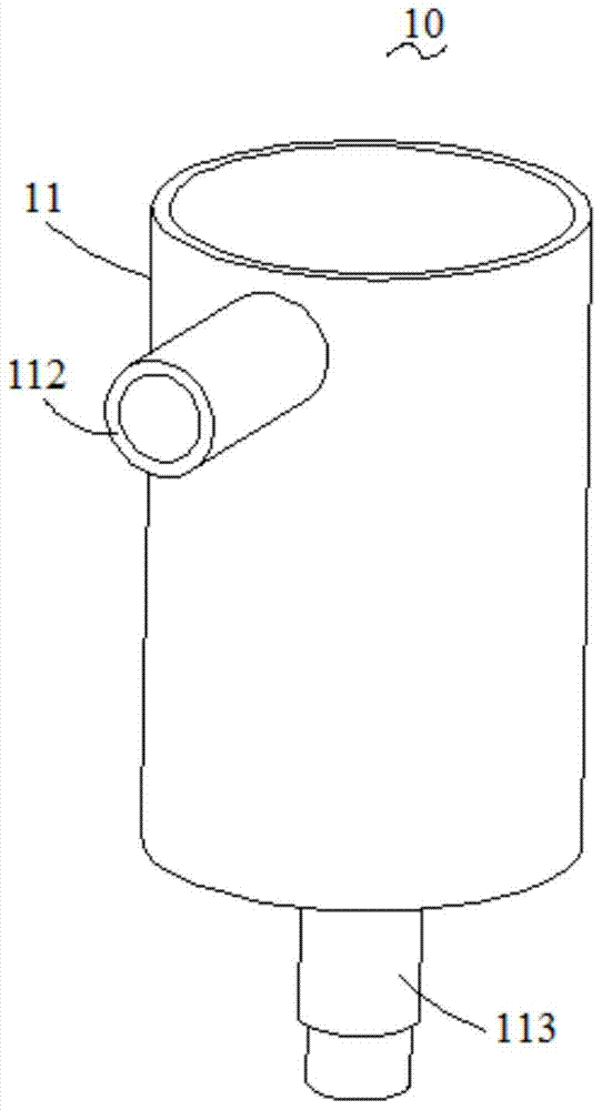
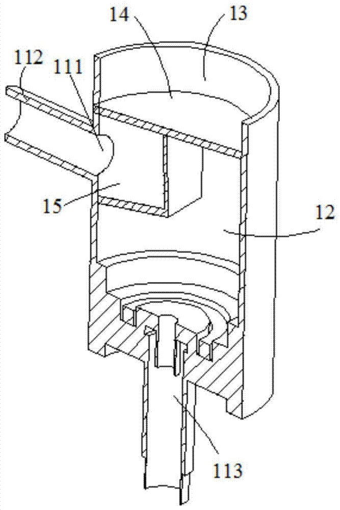
[0026] see Figure 1 to Figure 6 , a liquid detection system described in a preferred embodiment of the present invention includes a liquid detection device, a Raman spectrometer (not shown), a light trap (not shown), and signals from the Raman spectrometer and the light trap connected processor (not shown). The liquid detection device includes a liquid receiver 10 and a test pool 20 , the liquid receiver 10 communicates with the test pool 20 to introduce the liquid (not shown) in the liquid receiver 10 into the test pool 20 . The liquid receiver 10 includes a housing 11, a liquid storage chamber 12 and a transition chamber 13 formed in the housing 11, and a partition 14...


PUM


Abstract

The invention relates to a liquid automatic detection method, comprising: S1: a processor determines the quartz window to be selected, and the processor judges whether the quartz window on the current installation groove matches, if it matches, proceed to step S3; if not, Then go to step S2; S2: Start the pushing device to remove the quartz window from the installation groove, start the driving part, the driving part drives the bracket to rotate until the quartz window to be selected faces the installation groove, start the pushing device again, and the pushing device pushes the selected The sheet device moves to insert the quartz window sheet into the installation groove; S3: Start the drive device, the drive device drives the diversion water wheel to rotate forward, the diversion device guides the liquid into the liquid storage chamber, when the processor judges that there is liquid in the inspection chamber , start the Raman spectrometer and light trap for detection; S4: When the processor detects that the liquid reaches the detection amount, start the driving device to drive the diversion water wheel to reverse, and the diversion device guides the liquid into the return chamber.

Description

technical field [0001] The invention relates to a liquid automatic detection method. Background technique [0002] Raman spectrometers are commonly used in liquid detection, which analyzes various main components of liquids. When the existing Raman spectrometer is in use, it is necessary to set up a light trap and a test cell correspondingly. The liquid to be tested is installed in the test cell. The Raman spectrometer is set on one side to emit laser light, and the light trap is set on the other side of the test cell. , used to receive the laser in the inspection cell, and then analyze the various main components in the liquid by judging the received laser light. Raman spectrometers and light traps usually need to use quartz windows for liquid and Raman spectrometers and light traps. Separation, the reason for choosing quartz windows is that it can pass through far ultraviolet rays, which is the best of all ultraviolet materials, and can pass through visible light and near...

Claims


Application Information

Patent Timeline
Patent Type & Authority Patents(China)
IPC IPC(8): G01N21/65
Inventor 郑钢于涛于浩刘耀光秦绪阳
Owner SUZHOU EUROPOD PRECISION INSTR TECH CO LTD
Why Eureka
Try Eureka