
Liquid detection device

A detection device and liquid technology, applied in Raman scattering, material excitation analysis, etc., can solve the problems of cumbersome operation and time-consuming

Active Publication Date: 2015-10-28
SUZHOU EUROPOD PRECISION INSTR TECH CO LTD
View PDF12 Cites 3 Cited by
  • Summary
  • Abstract
  • Description
  • Claims
  • Application Information

AI Technical Summary

Problems solved by technology

When the existing Raman spectrometer is in use, it is necessary to set up a light trap and a test cell correspondingly. The liquid to be tested is installed in the test cell. The Raman spectrometer is set on one side to emit laser light, and the light trap is set on the other side of the test cell. , used to receive the laser in the test pool, and then analyze the various main components in the liquid by judging the received laser light. At present, when using a Raman spectrometer for testing, the liquid is manually introduced into the test pool and then tested. , but this method is time-consuming and cumbersome

Method used


Image

  • Liquid detection device
  • Liquid detection device
  • Liquid detection device

Examples


Embodiment Construction

[0019] The specific implementation manners of the present invention will be further described in detail below in conjunction with the accompanying drawings and embodiments. The following examples are used to illustrate the present invention, but are not intended to limit the scope of the present invention.

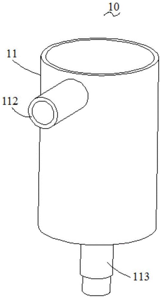
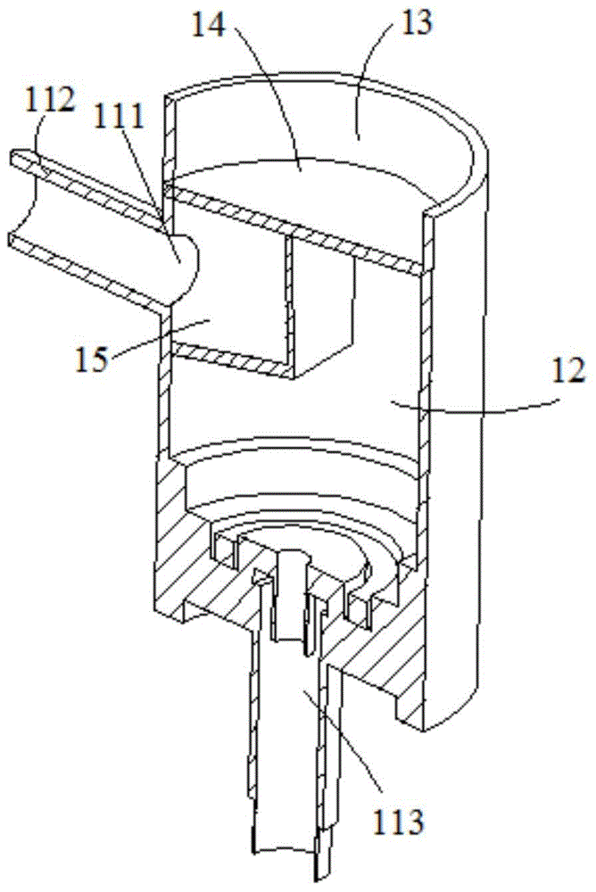
[0020] see Figure 1 to Figure 6 , a liquid detection system described in a preferred embodiment of the present invention includes a liquid detection device, a Raman spectrometer (not shown), a light trap (not shown), and signals from the Raman spectrometer and the light trap connected processor (not shown). The liquid detection device includes a liquid receiver 10 and a test pool 20 , the liquid receiver 10 communicates with the test pool 20 to introduce the liquid (not shown) in the liquid receiver 10 into the test pool 20 . The liquid receiver 10 includes a housing 11, a liquid storage chamber 12 and a transition chamber 13 formed in the housing 11, and a partition 14...


PUM


Abstract

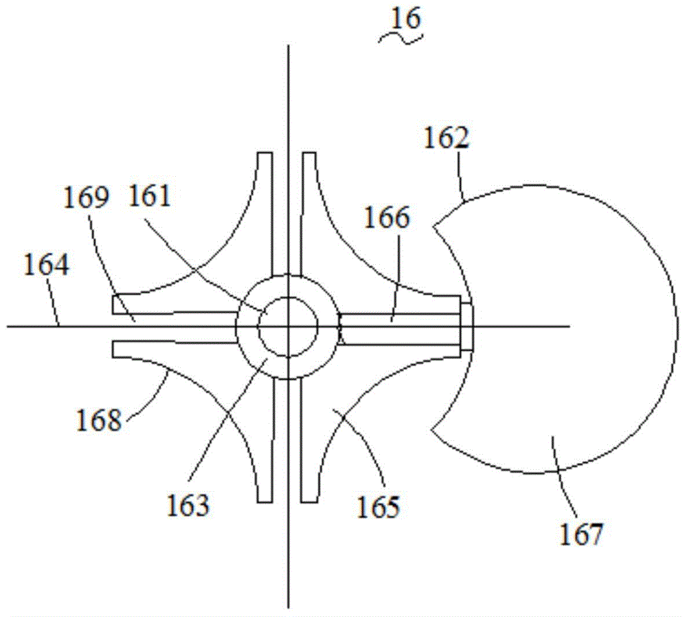
The invention relates to a liquid detection device which comprises a liquid receiving device and an inspection pool connected with the liquid receiving device, wherein the liquid receiving device comprises a housing, a liquid storage cavity, a transition cavity and a baffle; the liquid storage cavity and the transition cavity are arranged in the housing; the baffle is used for separating the transition cavity from the liquid storage cavity; the interior of the liquid storage cavity is divided to form a backflow cavity; a flow guide device is arranged on the liquid receiving device; the flow guide device comprises a flow guide water wheel and a drive device; the flow guide water wheel is arranged in the transition cavity; the drive device is used for driving the flow guide water wheel to rotate in the positive or negative direction; the flow guide water wheel comprises a rotating shaft and a blade; the blade extends outwards in the radial direction around the rotating shaft; the blade passes through the baffle; a first yielding opening and a second yielding opening, which allow the blade to pass through, are formed in the baffle; the transition cavity is communicated with the backflow cavity through the first yielding opening; the transition cavity is communicated with the liquid storage cavity through the second yielding opening; when the drive device is used for driving the flow guide water wheel to rotate in the forward direction, the flow guide water wheel guides liquid in the transition cavity in the backflow cavity from the first yielding opening; when the drive device is used for driving the flow guide water wheel to rotate in the negative direction, the flow guide water wheel guides liquid in the transition cavity in the liquid storage cavity from the second yielding opening; an inspection cavity is formed in the inspection pool.

Description

technical field [0001] The invention relates to a liquid detection device. Background technique [0002] Raman spectrometers are commonly used in liquid detection, which analyzes various main components of liquids. When the existing Raman spectrometer is in use, it is necessary to set up a light trap and a test cell correspondingly. The liquid to be tested is installed in the test cell. The Raman spectrometer is set on one side to emit laser light, and the light trap is set on the other side of the test cell. , used to receive the laser in the test pool, and then analyze the various main components in the liquid by judging the received laser light. At present, when using a Raman spectrometer for testing, the liquid is manually introduced into the test pool and then tested. , but this method is time-consuming and cumbersome to operate. Contents of the invention [0003] In order to solve the above technical problems, the object of the present invention is to provide a liq...

Claims


Application Information

Patent Timeline
Patent Type & Authority Applications(China)
IPC IPC(8): G01N21/65
Inventor 郑钢秦绪阳于涛于浩
Owner SUZHOU EUROPOD PRECISION INSTR TECH CO LTD
Learn More