Double-flow-rate water cap unit element

A single-unit, flow-rate technology, applied in the field of dual-flow water cap unit-units, can solve problems such as the inability to satisfy the ratio between the backwash flow rate and the filtration flow rate.

Inactive Publication Date: 2015-12-09
中国船舶集团有限公司第七零七研究所九江分部
View PDF5 Cites 0 Cited by
  • Summary
  • Abstract
  • Description
  • Claims
  • Application Information

AI Technical Summary

Problems solved by technology

Ordinary filter water caps cannot meet the speed ratio relationship between backwash flow rate and filter flow rate

Method used


Image

  • Double-flow-rate water cap unit element
  • Double-flow-rate water cap unit element
  • Double-flow-rate water cap unit element

Examples


Embodiment

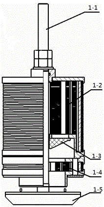
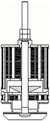
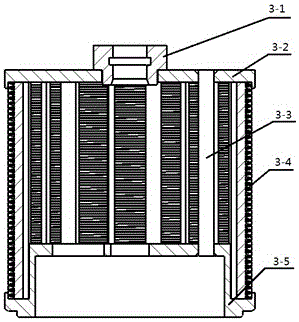
[0019] The device is composed of a high-speed flow part, a low-speed flow part, a square head screw, a valve core, a support block and a lock nut. The high and low speed flow parts are composed of upper and lower end covers, wire-wrapped screen tubes and tie rods for fastening the upper and lower end covers and screen tubes; the high speed flow parts are coaxial with the low speed flow parts, and the square head screw passes through The hole passes through, and the support block is placed on the other end of the water cap mounting plate, and is interlocked with the square end of the square head screw; the other end of the square head screw is a common thread, which is connected with the lock nut, and the high-speed through The flow part and the low-speed flow part are buckled on the water cap mounting plate; the valve core is placed between the high-speed flow part and the low-speed flow part through the square head screw rod, and can float up and down along the screw rod. The...


PUM


Abstract

The invention relates to a double-flow-rate water cap unit element, which comprises a square head screw rod, wherein the square head screw rod is connected with a low-speed through flow component and a valve core; one end of the square head screw rod is provided with a high-speed through flow component and a support block; the low-speed through flow component, the valve core and the high-speed through flow component are connected in series into a whole through the square head screw rod and is then fixedly arranged on an installing seat by a support block. The requirements under different process states of filter water flow rate and back flushing flow rate can be met through controlling the sieve pipe height of the high-speed through flow component and the low-speed through flow component. The double-flow-rate water cap unit element has the characteristics that the structure is simple, and the mounting and the dismounting are convenient.

Description

technical field [0001] The invention relates to a single element of a double-flow rate water cap. Background technique [0002] The water cap is a common filter interception device in the field of water treatment. When using resin for water treatment, water caps are basically used in the industry as parts for distributing water or intercepting resin. Conventional water caps are generally composed of upper and lower end caps, screen pipes, pull rods, support blocks or threaded handles, etc., and the upper and lower end caps clamp the screen pipes in the middle. When the tie rod and support block structure is adopted, the bottom of the tie rod passes through the upper and lower end covers, the screen tube, the water cap mounting plate and is interlocked with the support block in turn, and the top is pressed with a nut to fix the water cap on the mounting plate; the threaded handle is used During the structure, the threaded handle is generally integrated with the lower end co...

Claims


Application Information

Patent Timeline
Patent Type & Authority Applications(China)
IPC IPC(8): C02F1/00
Inventor 于少晖王李锋鄢恒飞柳堤张霞汤志鹏李拓张永红
Owner 中国船舶集团有限公司第七零七研究所九江分部
Why Eureka
Try Eureka