Fibre sensor assembly

An optical fiber sensor, optical fiber technology, applied in the field of bearings, can solve the problem of thermal damage of optical fiber sensors

Inactive Publication Date: 2015-12-02
AB SKF
View PDF16 Cites 11 Cited by
  • Summary
  • Abstract
  • Description
  • Claims
  • Application Information

AI Technical Summary

Problems solved by technology

However, using high temperature may cause thermal damage to the fiber optic sensor

Method used


Image

  • Fibre sensor assembly
  • Fibre sensor assembly
  • Fibre sensor assembly

Examples


Embodiment Construction

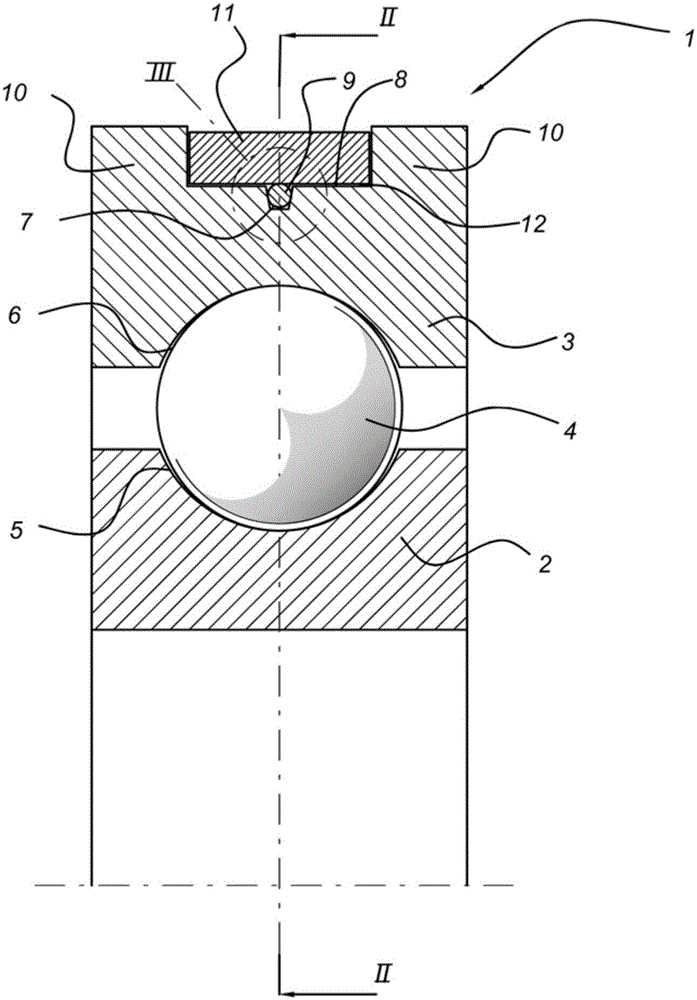
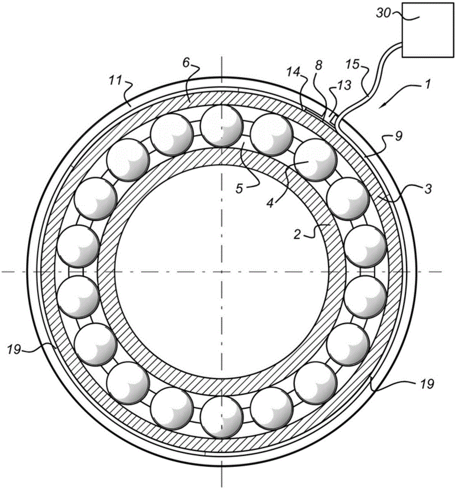
[0026] figure 1 An axial cross-section of the bearing 1 is shown, comprising an inner bearing ring 2 with inner raceways 5 and an outer bearing ring 3 with outer raceways 6 . Rolling elements 4 are arranged between the inner and outer rings 2, 3 so that the inner and outer bearing rings 2, 3 can rotate relative to each other. The rolling elements 4 are located between the inner and outer raceways 5 , 6 .

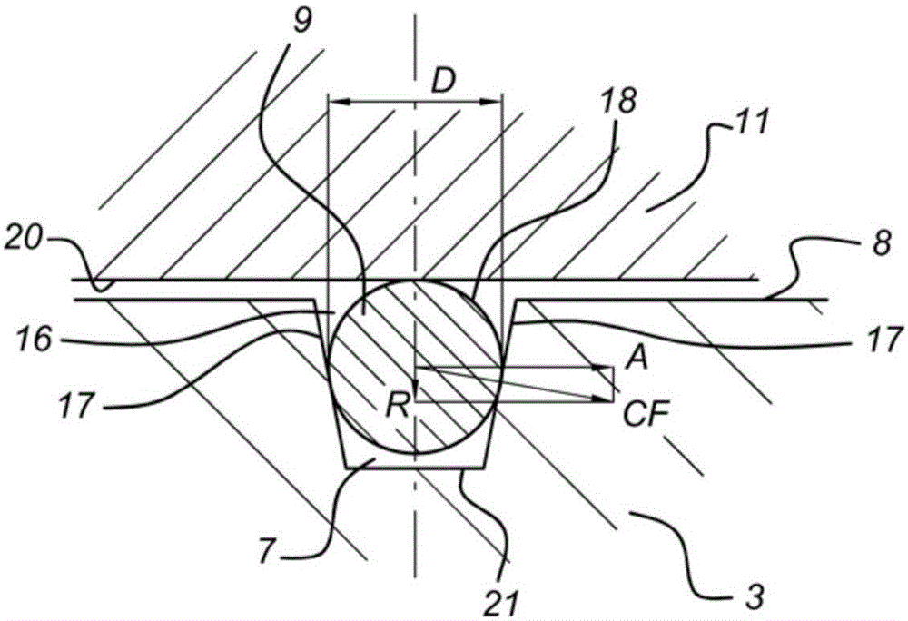
[0027]The grooves 7 are provided on the outer surface 8 of the outer bearing ring 3 . The groove 7 accommodates a fiber optic sensor 9, which includes an optical fiber. In turn, the grooves 7 are provided with channels 12 . The channel 12 is shaped as a recess between the two side walls 10 which form an increase in the thickness of the outer bearing ring 3 .

[0028] The fiber optic sensor 9 is accommodated in the groove 7 and is connected to the outer bearing ring by means of a clamping ring 11 . The clamping ring 11 is accommodated in the channel 12 . The clamping ri...


PUM


Abstract

A bearing which includes a bearing ring and rolling elements. The bearing ring includes an outer surface, having a groove around a circumference of the outer surface, wherein the groove is adapted to accommodate a fiber sensor. The bearing further comprises a clamping element, wherein the clamping element retains the fiber sensor with a clamping force acting in a radial direction of the bearing ring such that the fiber sensor intimately engages the bearing ring. Due to the clamping force, relative movement of the fiber sensor can be reduced.

Description

technical field [0001] The present invention relates to a bearing comprising a fiber optic sensor assembly, and also to a method of attaching such a fiber optic sensor to the bearing. Background technique [0002] Bearings are very important components in rotating machinery. If the bearing fails, the function of the machine may fail. In some applications, it can be very difficult or prohibitively expensive to replace a failed bearing outside of regular scheduled maintenance. These applications include deep sea applications, marine or continuous production lines. Condition monitoring is used when trying to predict when a bearing needs to be replaced before failure occurs. If the machine and bearing are in an easily accessible location, the condition of the bearing can be assessed, for example, by vibration measurements. For inaccessible equipment such as deep sea applications, other means are needed to assess the condition of the bearing so that it can be determined when ...

Claims


Application Information

Patent Timeline
Patent Type & Authority Applications(China)
IPC IPC(8): G01M11/08F16C19/52G01D5/353G01M13/04G02B6/36G01B11/16G01L1/24G01L5/00
CPCF16C41/00F16C19/522F16C43/04G01B11/16G01D5/353G01D5/35316G01D11/02G01L1/242G01L1/246G01L5/0009G01M11/085G01M13/04G02B6/3636Y10T29/4968F16C19/06
Inventor R.赫迪D.兰H.杨
Owner AB SKF
Why Eureka
Try Eureka